
Picolibc Version 1.0 Released
I wrote a couple of years ago about the troubles I had finding a good libc for embedded systems, and for the last year or so I've been using something I called 'newlib-nano', which was newlib with the stdio from avrlibc bolted on. That library has worked pretty well, and required very little work to ship.
Now that I'm doing RISC-V stuff full-time, and am currently working to improve the development environment on deeply embedded devices, I decided to take another look at libc and see if a bit more work on newlib-nano would make it a good choice for wider usage.
One of the first changes was to switch away from the very confusing "newlib-nano" name. I picked "picolibc" as that seems reasonably distinct from other projects in the space and and doesn't use 'new' or 'nano' in the name.
Major Changes
Let's start off with the big things I've changed from newlib:
Replaced stdio. In place of the large and memory-intensive stdio stack found in newlib, picolibc's stdio is derived from avrlibc's code. The ATmel-specific assembly code has been replaced with C, and the printf code has seen significant rework to improve standards conformance. This work was originally done for newlib-nano, but it's a lot cleaner looking in picolibc.
Switched from 'struct _reent' to TLS variables for per-thread values. This greatly simplifies the library and reduces memory usage for all applications -- per-thread data from unused portions of the library will not get allocated for any thread. On RISC-V, this also generates smaller and faster code. This also eliminates an extra level of function call for many code paths.
Switched to the 'meson' build system. This makes building the library much faster and also improves the maintainability of the build system as it eliminates a maze of twisty autotools configure scripts.
Updated the math test suite to use glibc as a reference instead of some ancient Sun machine.
Manually verified the test results to see how the library is doing; getting automated testing working will take a lot more effort as many (many) tests still have invalid 'correct' values resulting in thousands of failure.
Remove unused code with non-BSD licenses. There's still a pile of unused code hanging around, but all non-BSD licensed bits have been removed to make the licensing situation clear. Picolibc is BSD licensed.
Picocrt
Starting your embedded application requires initializing RAM as appropriate and calling initializers/constructors before invoking main(). Picocrt is designed to do that part for you.
Building Simplified
Using newlib-nano meant specifying the include and library paths very carefully in your build environment, and then creating a full custom linker script. With Picolibc, things are much easier:
Compile with -specs=picolibc.specs. That and the specification of the target processor are enough to configure include and library paths. The Debian package installs this in the gcc directory so you don't need to provide a full path to the file.
Link with picolibc.ld (which is used by default with picolibc.specs). This will set up memory regions and include Picocrt to initialize memory before your application runs.
Debian Packages
I've uploaded Debian packages for this version; they'll get stuck in the new queue for a while, but should eventually make there way into the repository. I'll plan on removing newlib-nano at some point in the future as I don't plan on maintaining both.
More information
You can find the source code on both my own server and over on github:
You'll find some docs and other information linked off the README file
AltOS 1.8.3 — TeleMega version 3.0 support and bug fixes
Bdale and I are pleased to announce the release of AltOS version 1.8.3.
AltOS is the core of the software for all of the Altus Metrum products. It consists of firmware for our cc1111, STM32L151, STMF042, LPC11U14 and ATtiny85 based electronics and Java-based ground station software.
This is a minor release of AltOS, including support for our new TeleMega v3.0 board and a selection of bug fixes
Announcing TeleMega v3.0
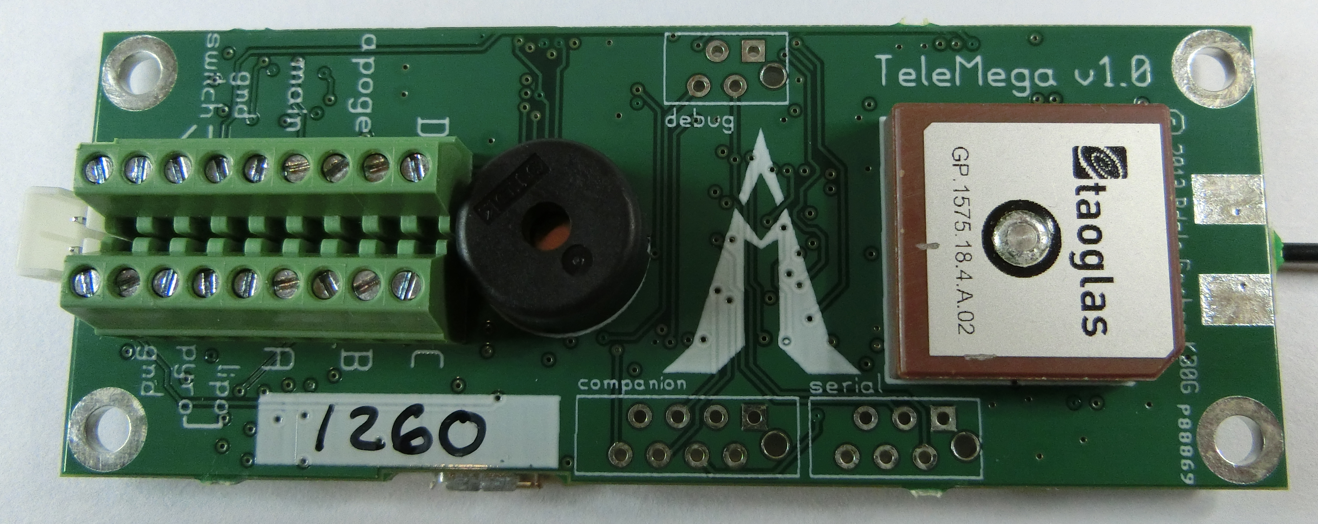
TeleMega is our top of the line flight computer with 9-axis IMU, 6 pyro channels, uBlox Max 7Q GPS and 40mW telemetry system. Version 3.0 is feature compatible with version 2.0, incorporating a new higher-perfomance 9-axis IMU in place of the former 6-axis IMU and separate 3-axis magnetometer.
AltOS 1.8.3
In addition to support for TeleMega v3.0 boards, AltOS 1.8.3 contains some important bug fixes for all flight computers. Users are advised to upgrade their devices.
Ground testing EasyMega and TeleMega additional pyro channels could result in a sticky 'fired' status which would prevent these channels from firing on future flights.
Corrupted flight log records could prevent future flights from capturing log data.
Fixed saving of pyro configuration that ended with 'Descending'. This would cause the configuration to revert to the previous state during setup.
The latest AltosUI and TeleGPS applications have improved functionality for analyzing flight data. The built-in graphing capabilities are improved with:
Graph lines have improved appearance to make them easier to distinguish. Markers may be placed at data points to show captured recorded data values.
Graphing offers the ability to adjust the smoothing of computed speed and acceleration data.
Exporting data for other applications has some improvements as well:
KML export now reports both barometric and GPS altitude data to make it more useful for Tripoli record reporting.
CSV export now includes TeleMega/EasyMega pyro voltages and tilt angle.
TeleMini V3.0 Dual-deploy altimeter with telemetry now available
TeleMini v3.0 is an update to our original TeleMini v1.0 flight computer. It is a miniature (1/2 inch by 1.7 inch) dual-deploy flight computer with data logging and radio telemetry. Small enough to fit comfortably in an 18mm tube, this powerful package does everything you need on a single board:
512kB on-board data logging memory, compared with 5kB in v1.
40mW, 70cm ham-band digital transceiver for in-flight telemetry and on-the-ground configuration, compared to 10mW in v1.
Transmitted telemetry includes altitude, speed, acceleration, flight state, igniter continutity, temperature and battery voltage. Monitor the state of the rocket before, during and after flight.
Radio direction finding beacon transmitted during and after flight. This beacon can be received with a regular 70cm Amateur radio receiver.
Barometer accurate to 100k' MSL. Reliable apogee detection, independent of flight path. Barometric data recorded on-board during flight. The v1 boards could only fly to 45k'.
Dual-deploy with adjustable apogee delay and main altitude. Fires standard e-matches and Q2G2 igniters.
0.5” x 1.7”. Fits easily in an 18mm tube. This is slightly longer than the v1 boards to provide room for two extra mounting holes past the pyro screw terminals.
Uses rechargeable Lithium Polymer battery technology. All-day power in a small and light-weight package.
Learn more at http://www.altusmetrum.org/TeleMini/
Purchase these at http://shop.gag.com/home-page/telemini-v3.html
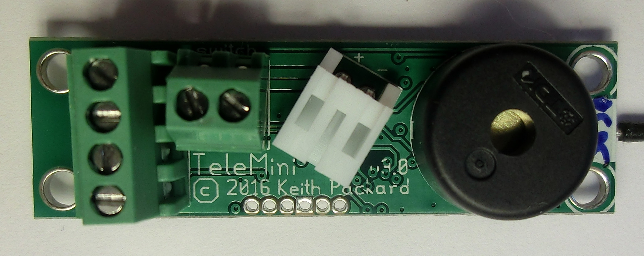
I don't have anything in these images to show just how tiny this board is—but the spacing between the screw terminals is 2.54mm (0.1in), and the whole board is only 13mm wide (1/2in).
This was a fun board to design. As you might guess from the version number, we made a couple prototypes of a version 2 using the same CC1111 SoC/radio part as version 1 but in the EasyMini form factor (0.8 by 1.5 inches). Feed back from existing users indicated that bigger wasn't better in this case, so we shelved that design.
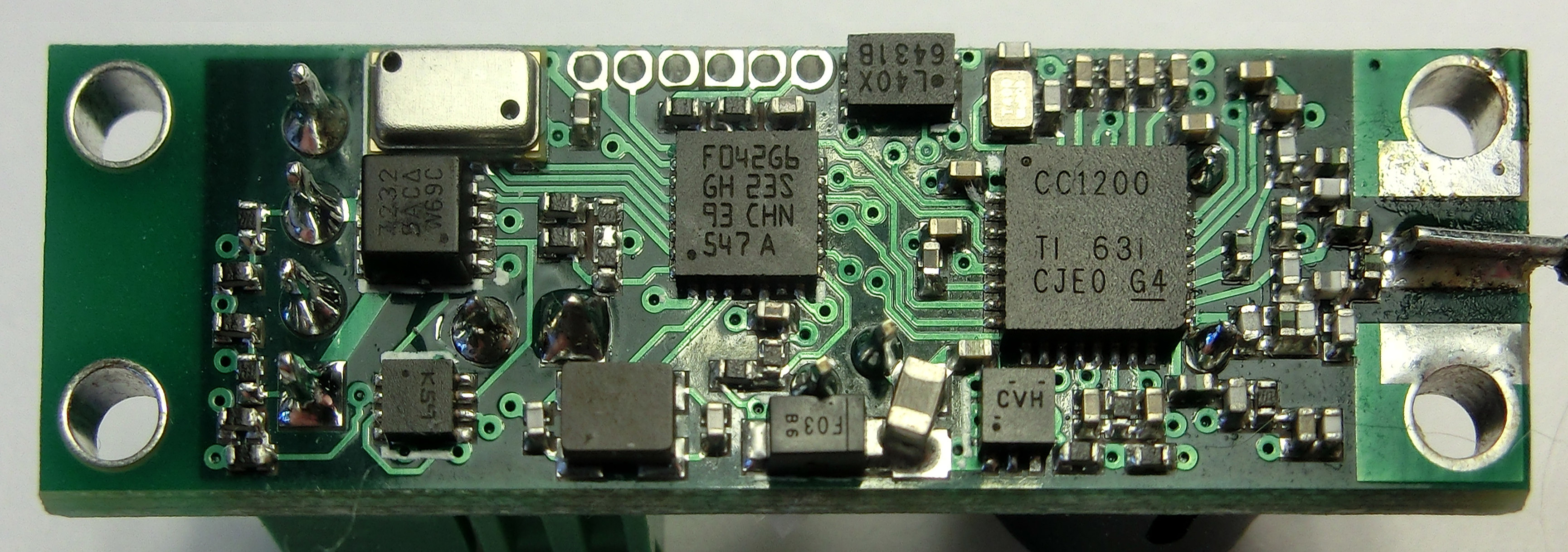
With the availability of the STM32F042 ARM Cortex-M0 part in a 4mm square package, I was able to pack that, the higher power CC1200 radio part, a 512kB memory part and a beeper into the same space as the original TeleMini version 1 board. There is USB on the board, but it's only on some tiny holes, along with the cortex SWD debugging connection. I may make some kind of jig to gain access to that for configuration, data download and reprogramming.
For those interested in an even smaller option, you could remove the screw terminals and battery connector and directly wire to the board, and replace the beeper with a shorter version. You could even cut the rear mounting holes off to make the board shorter; there are no components in that part of the board.
Finding a Libc for tiny embedded ARM systems
You'd think this problem would have been solved a long time ago. All I wanted was a C library to use in small embedded systems -- those with a few kB of flash and even fewer kB of RAM.
Small system requirements
A small embedded system has a different balance of needs:
Stack space is limited. Each thread needs a separate stack, and it's pretty hard to move them around. I'd like to be able to reliably run with less than 512 bytes of stack.
Dynamic memory allocation should be optional. I don't like using malloc on a small device because failure is likely and usually hard to recover from. Just make the linker tell me if the program is going to fit or not.
Stdio doesn't have to be awesomely fast. Most of our devices communicate over full-speed USB, which maxes out at about 1MB/sec. A stdio setup designed to write to the page cache at memory speeds is over-designed, and likely involves lots of buffering and fancy code.
Everything else should be fast. A small CPU may run at only 20-100MHz, so it's reasonable to ask for optimized code. They also have very fast RAM, so cycle counts through the library matter.
Available small C libraries
I've looked at:
μClibc. This targets embedded Linux systems, and also appears dead at this time.
musl libc. A more lively project; still, definitely targets systems with a real Linux kernel.
dietlibc. Hasn't seen any activity for the last three years, and it isn't really targeting tiny machines.
newlib. This seems like the 'normal' embedded C library, but it expects a fairly complete "kernel" API and the stdio bits use malloc.
avr-libc. This has lots of Atmel assembly language, but is otherwise ideal for tiny systems.
pdclib. This one focuses on small source size and portability.
Current AltOS C library
We've been using pdclib for a couple of years. It was easy to get running, but it really doesn't match what we need. In particular, it uses a lot of stack space in the stdio implementation as there's an additional layer of abstraction that isn't necessary. In addition, pdclib doesn't include a math library, so I've had to 'borrow' code from other places where necessary. I've wanted to switch for a while, but there didn't seem to be a great alternative.
What's wrong with newlib?
The "obvious" embedded C library is newlib. Designed for embedded systems with a nice way to avoid needing a 'real' kernel underneath, newlib has a lot going for it. Most of the functions have a good balance between speed and size, and many of them even offer two implementations depending on what trade-off you need. Plus, the build system 'just works' on multi-lib targets like the family of cortex-m parts.
The big problem with newlib is the stdio code. It absolutely requires dynamic memory allocation and the amount of code necessary for 'printf' is larger than the flash space on many of our devices. I was able to get a cortex-m3 application compiled in 41kB of code, and that used a smattering of string/memory functions and printf.
How about avr libc?
The Atmel world has it pretty good -- avr-libc is small and highly optimized for atmel's 8-bit avr processors. I've used this library with success in a number of projects, although nothing we've ever sold through Altus Metrum.
In particular, the stdio implementation is quite nice -- a 'FILE' is effectively a struct containing pointers to putc/getc functions. The library does no buffering at all. And it's tiny -- the printf code lacks a lot of the fancy new stuff, which saves a pile of space.
However, much of the places where performance is critical are written in assembly language, making it pretty darn hard to port to another processor.
Mixing code together for fun and profit!
Today, I decided to try an experiment to see what would happen if I used the avr-libc stdio bits within the newlib environment. There were only three functions written in assembly language, two of them were just stubs while the third was a simple ultoa function with a weird interface. With those coded up in C, I managed to get them wedged into newlib.
Figuring out the newlib build system was the only real challenge; it's pretty awful having generated files in the repository and a mix of autoconf 2.64 and 2.68 version dependencies.
The result is pretty usable though; my STM 32L discovery board demo application is only 14kB of flash while the original newlib stdio bits needed 42kB and that was still missing all of the 'syscalls', like read, write and sbrk.
Here's gitweb pointing at the top of the tiny-stdio tree:
And, of course you can check out the whole thing
git clone git://keithp.com/git/newlib
'master' remains a plain upstream tree, although I do have a fix on that branch. The new code is all on the tiny-stdio branch.
I'll post a note on the newlib mailing list once I've managed to subscribe and see if there is interest in making this option available in the upstream newlib releases. If so, I'll see what might make sense for the Debian libnewlib-arm-none-eabi packages.
AltOS 1.6.3 —
Bdale and I are pleased to announce the release of AltOS version 1.6.3.
AltOS is the core of the software for all of the Altus Metrum products. It consists of firmware for our cc1111, STM32L151, STMF042, LPC11U14 and ATtiny85 based electronics and Java-based ground station software.
Version 1.6.3 adds idle mode to AltosDroid and has bug fixes for our host software on desktops, laptops an android devices along with BlueTooth support for Windows.
1.6.3 is in Beta test for Android; if you want to use the beta version, join the AltosDroid beta program
AltOS
AltOS fixes:
- Fix hardware flow control on TeleBT v3.0. RTS/CTS is wired backwards on this board, switch from using the hardware to driving these pins with software.
AltosUI and TeleGPS Applications
AltosUI and TeleGPS New Features:
- Add BlueTooth support for Windows operating system. This supports connections to TeleBT over BlueTooth rather than just USB.
AltosUI and TeleGPS Fixes:
Change Java detection and install on Windows. Detection is now done by looking for the 'javaw.exe' program, and installation by opening a browser on the java.com web site.
Delay polling while the Fire Igniters is visible to allow for TeleMega to report back complete status over the radio.
Disallow changing RF calibration numbers in the configuration UI. There's no good reason to change this from the field, and recovering is really hard if you haven't written down the right number.
Fix USB device discovery on Mac OS X El Capitan. This makes the connected Altus Metrum USB devices appear again.
Fix acceleration data presented in MonitorIdle mode for TeleMetrum v2.0 flight computers.
AltosDroid
AltosDroid new features:
Monitor Idle mode. Check state of flight computer while in idle mode over the radio link
Fire Igniters. Remotely fire ignires for recovery system ground tests.
Remote reboot. Cause the flight computer to reboot over the radio link. This provides a method for switching the flight computer from idle to flight mode without needing to reach the power switch.
Configurable frequency menu. Change the set of available frequencies and provide more descriptive names.
AltosDroid bug fixes:
Don't set target location if GPS hasn't locked yet.
Fix saving target states so they can be reloaded when the application restarts. When the application is shut down and restarted, all previous target state information will be restored (including GPS position if available).
Fix crash on some Android devices for offline maps when changing the map scale or location.
Don't require USB OTG support. This kept the latest AltosDroid from being offered on devices without USB device support, although it can work without that just fine using BlueTooth.
Don't require bluetooth to be enabled. This allows the application to operate with USB devices or just show old data without turning on the bluetooth radio.
Recover old tracker positions when restarting application. This finally allows you to safely stop and restart the application without losing the last known location of any tracker.
Documentation
- Document TeleMega and EasyMega additional pyro channel continuity audio alert pattern.
AltOS 1.6.2 — TeleMega v2.0 support, bug fixes and documentation updates
Bdale and I are pleased to announce the release of AltOS version 1.6.2.
AltOS is the core of the software for all of the Altus Metrum products. It consists of firmware for our cc1111, STM32L151, STMF042, LPC11U14 and ATtiny85 based electronics and Java-based ground station software.
This is a minor release of AltOS, including support for our new TeleMega v2.0 board, a small selection of bug fixes and a major update of the documentation
AltOS Firmware — TeleMega v2.0 added
The updated six-channel flight computer, TeleMega v2.0, has a few changes from the v1.0 design:
CC1200 radio chip instead of the CC1120. Better receive performance for packet mode, same transmit performance.
Serial external connector replaced with four PWM channels for external servos.
Companion pins rewired to match EasyMega functionality.
None of these change the basic functionality of the device, but they do change the firmware a bit so there's a new package.
AltOS Bug Fixes
We also worked around a ground station limitation in the firmware:
- Slow down telemetry packets so receivers can keep up. With TeleMega v2 offering a fast CPU and faster radio chip, it was overrunning our receivers so a small gap was introduced between packets.
AltosUI and TeleGPS applications
A few minor new features are in this release
Post-flight TeleMega and EasyMega orientation computations were off by a factor of two
Downloading eeprom data from flight hardware would bail if there was an error in a data record. Now it keeps going.
Documentation
I spent a good number of hours completely reformatting and restructuring the Altus Metrum documentation.
I've changed the source format from raw docbook to asciidoc, which has made it much easier to edit and to use docbook features like links.
The css moves the table of contents out to a sidebar so you can navigate the html format easily.
There's a separate EasyMini manual now, constructed by taking sections from the larger manual.
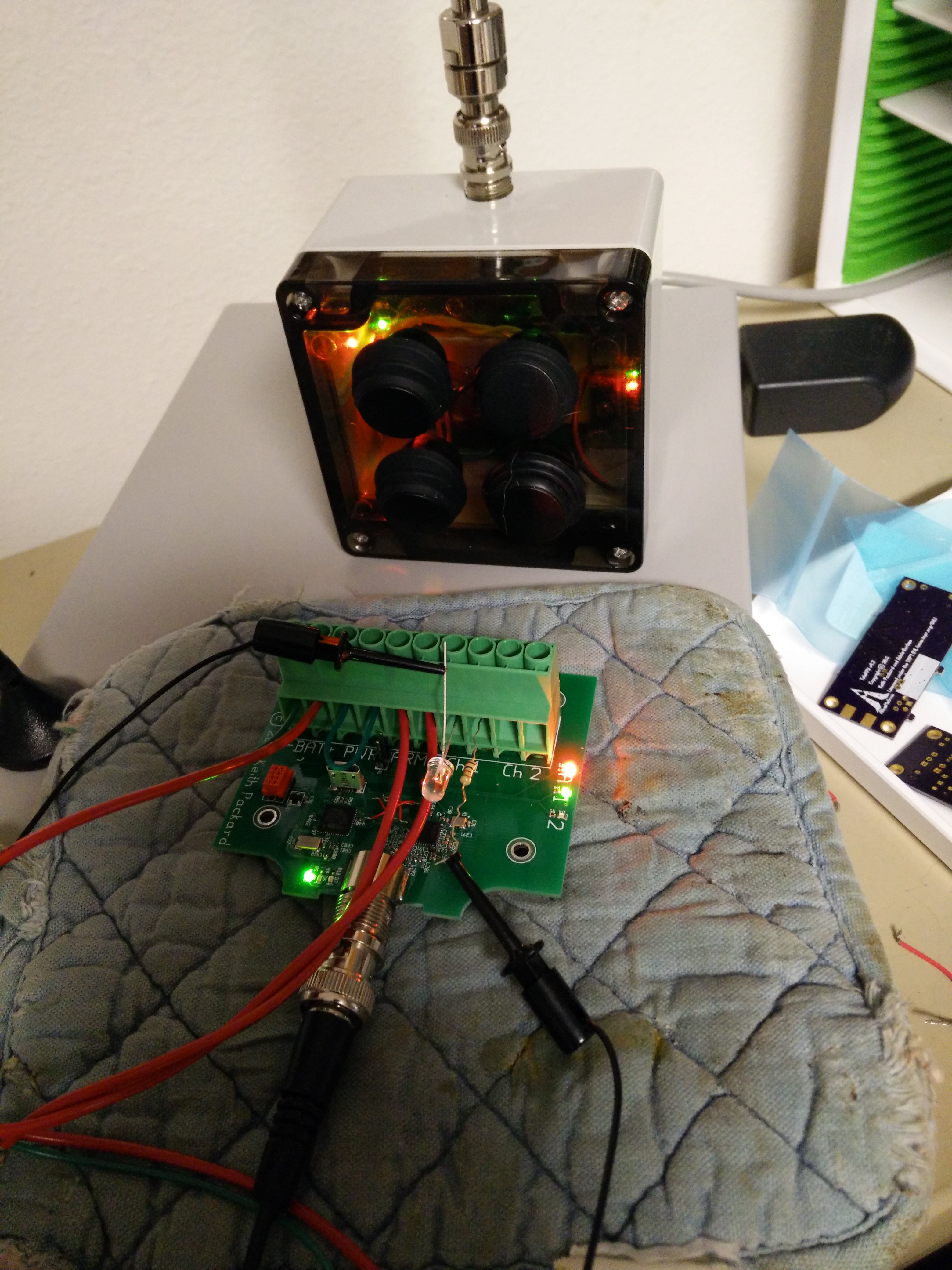
TeleLaunchTwo — A Smaller Wireless Launch Controller
I've built a wireless launch control system for NAR and OROC. Those are both complex systems with a single controller capable of running hundreds of pads. And, it's also complicated to build, with each board hand-made by elves in our Portland facility (aka, my office).
A bunch of people have asked for something simpler, but using the same AES-secured two-way wireless communications link, so I decided to just build something and see if we couldn't eventually come up with something useful. I think if there's enough interest, I can get some boards built for reasonable money.
Here's a picture of the system; you can see the LCO end in a box behind the pad end sitting on the bench.
Radio Link
Each end has a 35mW 70cm digital transceiver (so, they run in the 440MHz amateur band). These run at 19200 baud with fancy forward error correction and AES security to keep the link from accidentally (or maliciously) firing a rocket at the wrong time. Using a bi-directional link, we also get igniter continuity and remote arming information at the LCO end.
The LCO Box
In the LCO box, there's a lipo battery to run the device, so it can be completely stand-alone. It has three switches and a button -- an arming switch for each of two channels, a power switch and a firing button. The lipo can be charged by opening up the box and plugging it into a USB port.
The Pad Box
The pad box will have some cable glands for the battery and each firing circuit. On top, it will have two switches, a power switch and an arming switch. The board has two high-power FETs to drive the igniters. That should be more reliable than using a relay, while also allowing the board to tolerate a wider range of voltages -- the pad box can run on anything from 12V to 24V.
The Box
Unlike the OROC and NAR systems, these boards are both designed to fit inside a specific box, the Hammond 1554E, and use the mounting standoffs provided. This box is rated at NEMA 4X, which means it's fairly weather proof. Of course, I have to cut holes in the box, but I found some NEMA 4X switches, will use cable glands for the pad box wiring and can use silicone around the BNC connector. The result should be pretty robust. I also found a pretty solid-seeming BNC connector, which hooks around the edge of the board and also clips on to the board.
Safety Features.
There's an arming switch on both ends of the link, and you can't fire a rocket without having both ends armed. That provides an extra measure of safety while working near the pad. The pad switch is a physical interlock between the power supply and the igniters, so even if the software is hacked or broken, disarming the box means the igniters won't fire.
The LCO box beeps constantly when either arming switch is selected, giving you feedback that the system is ready to fire. And you can see on any LED whether the pad box is also armed.
AltOS 1.6 — TeleDongle v3.0 support and bug fixes
Bdale and I are pleased to announce the release of AltOS version 1.6.
AltOS is the core of the software for all of the Altus Metrum products. It consists of firmware for our cc1111, STM32L151, STMF042, LPC11U14 and ATtiny85 based electronics and Java-based ground station software.
This is a major release of AltOS, including support for our new TeleDongle v3.0 board and a selection of bug fixes
AltOS Firmware — TeleDongle v3.0 added along with some fixes
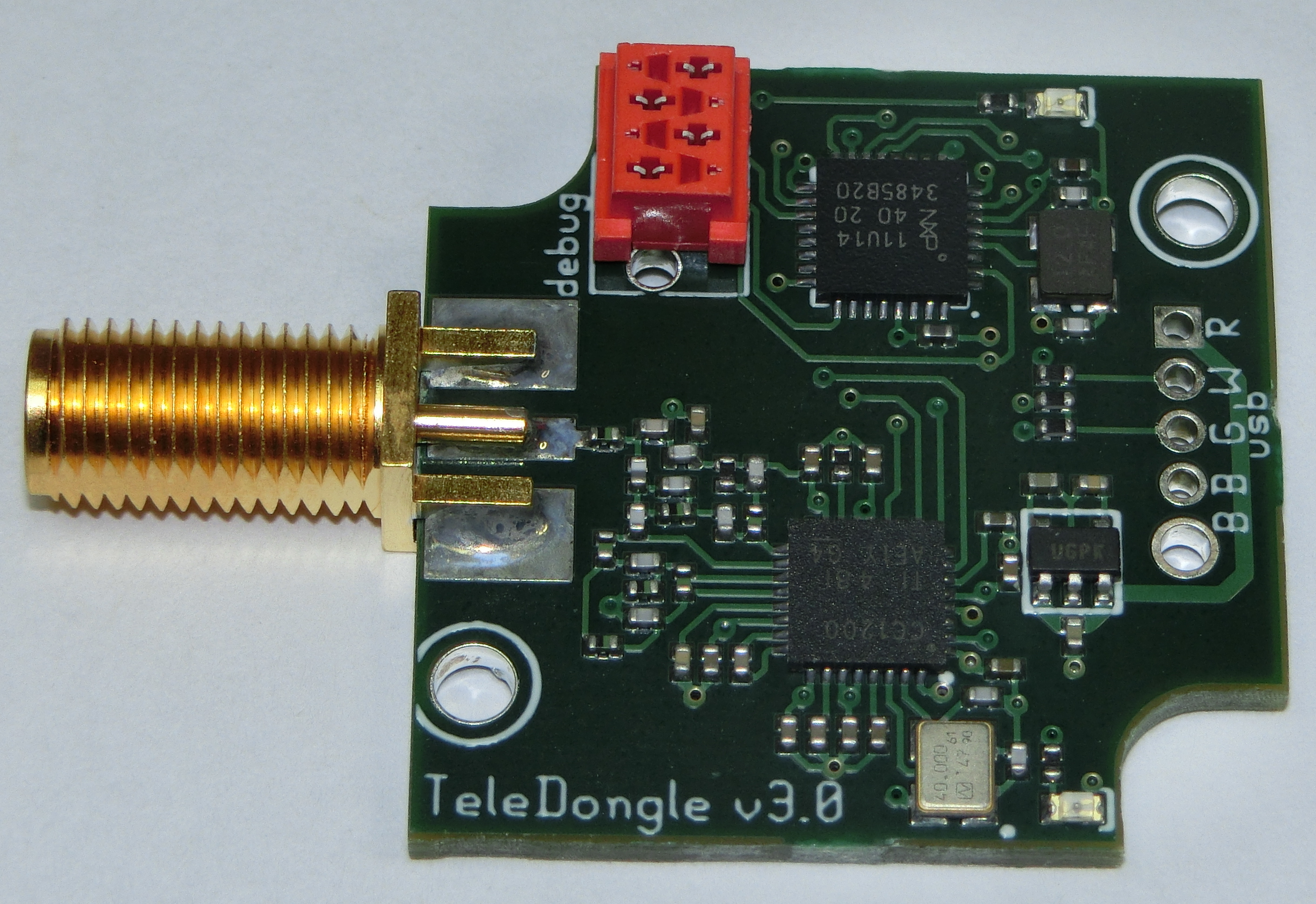
Our updated ground station, TeleDongle v3.0, works just like the original TeleDongle, but is an all-new design:
CC1200 radio chip is about 5dB more sensitive than TeleDongle's CC1111.
LPC11U14 CPU can be reprogrammed over the USB link.
AltOS Bug Fixes
We also fixed a few bugs in the firmware:
Make sure the startup flight computer beeps are consistent. Sometimes, it was taking long enough to beep out the battery voltage that the flight computer state was changing in the middle, causing a bit of confusion.
Change TeleDongle's LED indicators during telemetry reception. The green LED blinks on successful packet reception, and the red LED blinks when a packet with an invalid checksum is received.
The SPI driver used in both TeleDongle v3 and TeleGPS has been rewritten to avoid locking up under heavy CPU load. If you've got a TeleGPS board, you'll want to reflash with new firmware.
AltosUI and TeleGPS applications
A few minor new features are in this release
AltosUI can now compute and display tilt angle when graphing eeprom log data from TeleMega and EasyMega.
The AltosUI tool window is shown when starting with a data file. This way, when you double-click on a file in the file manager, you'll get the whole AltosUI interface, rather than just the graphing window.
At the end of replaying an old log file, stick 'done' in the Age field so you can tell the recording is over.
Bug Fixes
There are a bunch of minor bug fixes, including the usual collection of attempts to make stuff behave better on Windows platforms.
Use a different Windows API to discover USB device ids. This works better on my new HP Windows 7 machine. Maybe it will work better for other people too?
Look in more places in the Windows registry to try and find the installed Java version. It appears that the default Java download from Oracle is a 32-bit version? In any case, that version sticks its install information in a different spot in the registry.
Fix file associations on Windows when Java isn't installed in the system root.
Make 'Scan Channels' work better with new AltOS firmware which only reports device configuration information once ever five seconds.
Altus Metrum's 2014 Black Friday Event
BLACK FOREST, Colorado USA
Altus Metrum announces two special offers for "Black Friday" 2014.
We are pleased to announce that both TeleMetrum and TeleMega will be back in stock and available for shipment before the end of November. To celebrate this, any purchase of a TeleMetrum, TeleMega, or EasyMega board will include, free of charge, one each of our 160, 400, and 850 mAh Polymer Lithium Ion batteries and a free micro USB cable!
- http://shop.gag.com/black-friday/bf-easymega.html
- http://shop.gag.com/black-friday/bf-telemega.html
- http://shop.gag.com/black-friday/bf-telemetrum.html
To celebrate NAR's addition of our 1.9 gram recording altimeter, MicroPeak, to the list of devices approved for use in contests and records, and help everyone get ready for NARAM 2015's altitude events, purchase 4 MicroPeak boards and we'll throw in a MicroPeak USB adapter for free!
These deals will be available from 00:00 Friday, 28 November 2014 through 23:59 Monday, 1 December, 2014. Only direct sales through our web store at http://shop.gag.com are included; no other discounts apply.
Find more information on all Altus Metrum products at http://altusmetrum.org.
Thank you for your continued support of Altus Metrum in 2014. We continue to work on more cool new products, and look forward to meeting many of you on various flight lines in 2015!
Neil Anderson Flies EasyMega to 118k' At BALLS 23
Altus Metrum would like to congratulate Neil Anderson and Steve Cutonilli on the success the two stage rocket, “A Money Pit”, which flew on Saturday the 20th of September on an N5800 booster followed by an N1560 sustainer.
“A Money Pit” used two Altus Metrum EasyMega flight computers in the sustainer, each one configured to light the sustainer motor and deploy the drogue and main parachutes.
Safely Staged After a 7 Second Coast
After the booster burned out, the rocket coasted for 7 seconds to 250m/s, at which point EasyMega was programmed to light the sustainer. As a back-up, a timer was set to light the sustainer 8 seconds after the booster burn-out. In both cases, the sustainer ignition would have been inhibited if the rocket had tilted more than 20° from vertical. During the coast, the rocket flew from 736m to 3151m, with speed going from 422m/s down to 250m/s.
This long coast, made safe by EasyMega's quaternion-based tilt sensor, allowed this flight to reach a spectacular altitude.
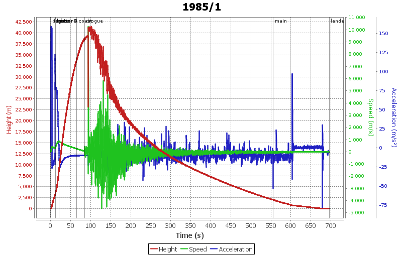
Apogee Determined by Accelerometer
Above 100k', the MS5607 barometric sensor is out of range. However, as you can see from the graph, the barometric sensor continued to return useful data. EasyMega doesn't expect that to work, and automatically switched to accelerometer-only apogee determination mode.
Because off-vertical flight will under-estimate the time to apogee when using only an accelerometer, the EasyMega boards were programmed to wait for 10 seconds after apogee before deploying the drogue parachute. That turned out to be just about right; the graph shows the barometric data leveling off right as the apogee charges fired.
Fast Descent in Thin Air
Even with the drogue safely fired at apogee, the descent rate rose to over 200m/s in the rarefied air of the upper atmosphere. With increasing air density, the airframe slowed to 30m/s when the main parachute charge fired at 2000m. The larger main chute slowed the descent further to about 16m/s for landing.