
MicroPeak Serial Interface — Flight Logging for MicroPeak
MicroPeak was original designed as a simple peak-recording altimeter. It displays the maximum height of the last flight by blinking out numbers on the LED.
Peak recording is fun and easy, but you need a log across apogee to check for unexpected bumps in baro data caused by ejection events. NAR also requires a flight log for altitude records. So, we wondered what could be done with the existing MicroPeak hardware to turn it into a flight logging altimeter.
Logging the data
The 8-bit ATtiny85 used in MicroPeak has 8kB of flash to store the executable code, but it also has 512B (yes, B as in "bytes") of eeprom storage for configuration data. Unlike the code flash, the little eeprom can be rewritten 100,000 times, so it should last for a lifetime of rocketry.
The original MicroPeak firmware already used that to store the average ground pressure and minimum pressure (in Pascals) seen during flight; those are used to compute the maximum height that is shown on the LED. If we store just the two low-order bytes of the pressure data, we'd have room left for 251 data points. That means capturing data at least every 32kPa, which is about 3km at sea level.
251 points isn't a whole lot of storage, but we really only need to capture the ascent and arc across apogee, which generally occurs within the first few seconds of flight.
MicroPeak samples air pressure once every 96ms, if we record half of those samples, we'll have data every 192ms. 251 samples every 192ms captures 48 seconds of flight. A flight longer than that will just see the first 48 seconds. Of course, if apogee occurs after that limit, MicroPeak will still correctly record that value, it just won't have a continuous log.
Downloading the data
Having MicroPeak record data to the internal eeprom is pretty easy, but it's not a lot of use if you can't get the data into your computer. However, there aren't a whole lot of interfaces avaialble on MicroPeak. We've only got:
The 6-pin AVR programming header. This is how we load firmware onto MicroPeak during manufacturing. It's not locked (of course), and the hardware supports reading and writing of flash, ram and eeprom.
The LED. We already use this to display the maximum height of the previous flight, can we blink it faster and then get the computer to read it out?
First implementation
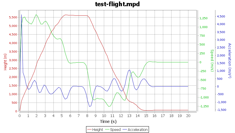
I changed the MicroPeak firmware to capture data to eeprom and made a 'test flight' using my calibrated barometric chamber (a large syringe). I was able to read out the flight data using the AVR programming pins and got the flight logging code working that way.
The plots I created looked great, but using an AVR programmer to read the data looked daunting for most people as it requires:
An AVR programmer. Adafruit sells the surprisingly useful USBtinyISP programmer. There are Windows drivers available for this, and you can get the necessary avrdude binaries from the usbtiny page above. The programmer itself comes in kit form, so you have to solder it together. There are other programmers available for a bit more than come pre-assembled, but all of them require that you wander around the net finding the necessary drivers and programming software.
A custom MicroPeak programming jig. We have these for sale in the Altus Metrum web store but, because they need special pogo pins and a pile of custom circuit boards, they're not cheap to make.
With the hardware running at least $120 retail, and requiring a pile of software installed from various places around the net, this approach didn't seem like a great way to let people easily capture flight data from their tiny altimeter.
The Blinking LED
The only other interface available is the MicroPeak LED. It's a nice LED, bright and orange and low power. But, it's still just a single LED. However, it seemed like it might be possible to have it blink out the data and create a device to watch the LED and connect that to a USB port.
The simplest idea I had was to just blink out the data in asynchronous serial form; a start bit, 8 data bits and a stop bit. On the host side, I could use a regular FTDI FT230 USB to serial converter chip. Those even have a 3.3V regulator and can supply a bit of current to other components on the board, eliminating the need for an external power supply.
To 'see' the LED blink, I needed a photo-transistor that actually responds to the LED's wavelength. Most photo-transistors are designed to work with infrared light, which nicely makes the whole setup invisible. There are a few photo-transistors available which do respond in the visible range, and ROHM RPM-075PT actually has its peak sensitivity right in the same range as the LED.
In between the photo-transistor and the FT230, I needed a detector circuit which would send a '1' when the light was present and a '0' when it wasn't. To me, that called for a simple comparator made from an op-amp. Set the voltage on the negative input to somewhere between 'light' and 'dark' and then drive the positive input from the photo-transistor; the output would swing from rail to rail.
Bit-banging async
The ATtiny85 has only a single 'serial port', which is used on MicroPeak to talk to the barometric sensor in SPI mode. So, sending data out the LED requires that it be bit-banged — directly modulated with the CPU.
I wanted the data transmission to go reasonably fast, so I picked a rate of 9600 baud as a target. That means sending one bit every 104µS. As the MicroPeak CPU is clocked at only 250kHz, that leaves only about 26 cycles per bit. I need all of the bits to go at exactly the same speed, so I pack the start bit, 8 data bits and stop bit into a single 16 bit value and then start sending.
Of course, every pass around the loop would need to take exactly the same number of cycles, so I carefully avoided any conditional code. With that, 14 of the 26 cycles were required to just get the LED set to the right value. I padded the loop with 12 nops to make up the remaining time.
At 26 cycles per bit, it's actually sending data at a bit over 9600 baud, but the FT230 doesn't seem to mind.
A bit of output structure
I was a bit worried about the serial converter seeing other light as random data, so I prefixed the data transmission with 'MP'; that made it easy to ignore anything before those two characters as probably noise.
Next, I decided to checksum the whole transmission. A simple 16-bit CRC would catch most small errors; it's easy enough to re-try the operation if it fails after all.
Finally, instead of sending the data in binary, I displayed each byte as two hex digits, and sent some newlines along to keep the line lengths short. This makes it easy to ship flight logs in email or whatever.
Here's a sample of the final data format:
MP
dc880100fec000006800f56d8f63b059
73516447273fa93728301927d91b7712
730bbf0491fe88f7c5ee8ee896e3fadc
9dd9d3d502d1afcea2cbafc6b4c34ec1
bfbfcabf10c03dc05dc070c084c08fc0
9cc0abc0b9c0c1c0ccc0dcc020c152c4
71c9a6cf45d623db7de05ee758edd9f2
b4f9fd00aa074311631a9221c4291330
c035873b2943084bbb52695c0c67eb6b
d26ee5707472fb74a4781f7dee802b84
09860a87e786ad868a866e8659865186
4e8643863e863986368638862e862d86
2f862d86298628862a86268629862686
28862886258625862486
d925
Making the photo-transistor go fast enough
The photo-transistor acts as one half of a voltage divider on the positive op-amp terminal, with a resistor making the other half. However, the photo-transistor acts a bit like a capacitor, so when I initially chose a fairly large value for the resistor, it actually took too long to switch between on and off -- the transistor would spend a bunch of time charging and discharging. I had to reduce the resistor to 1kΩ for the circuit to work.
Remaining hardware design
I prototyped the circuit on a breadboard using a through-hole op-amp that my daughter designed into her ultrasonic guided robot and a prefabricated FTDI Friend board. I wanted to use the target photo-transistor, so I soldered a couple of short pieces of wire onto the SMT pads and stuck that into the breadboard.
Once I had that working, I copied the schematic to gschem, designed a board and had three made at OSHPark for the phenomenal sum of $1.35.
Aside from goofing up on the FT230 USB data pins (swapping D+ and D-), the board worked perfectly.
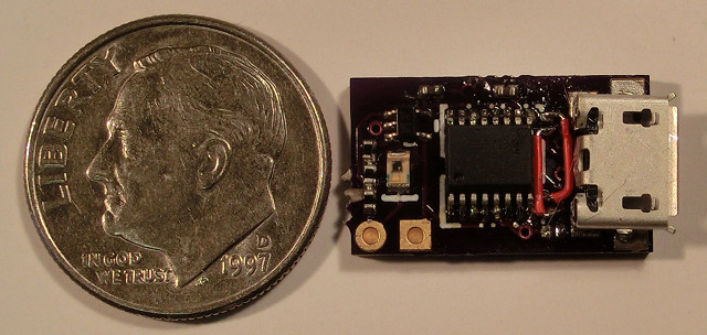
The final hardware design includes an LED connected to the output of the comparator that makes it easier to know when things are lined up correctly, otherwise it will be essentially the same.
Host software
Our AltosUI code has taught us a lot about delivering code that runs on Linux, Mac OS X and Windows, so I'm busy developing something based on the same underlying Java bits to support MicroPeak. Here's a sample of the graph results so far:
Production plans
I've ordered a couple dozen raw boards from OSH Park, and once those are here, I'll build them and make them available for sale in a couple of weeks. The current plan is to charge $35 for the MicroPeak serial interface board, or sell it bundled with MicroPeak for $75.