
Introducing TeleMetrum v0.2
Bdale and I (mostly Bdale, of course) finished the TeleMetrum v0.2 design work in December, and this weekend we got boards made and parts ordered and Bdale sat down with his trusty electric skillet and built 3 new boards. The new design has an integrated GPS receiver and patch antenna, and is otherwise fairly similar in design to v0.1.
TeleMetrum v0.2 Hardware
Here's the front side of the board:
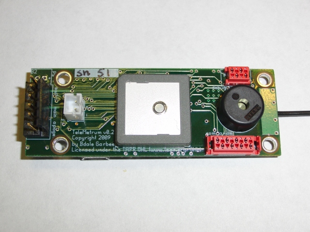
From the left, you'll see a connector for an external power switch and the two ejection charge circuits, a battery connector for a single 3.7V lipo cell, the GPS patch antenna, a 4-pin debug connector, the piezo buzzer and the new 8-pin companion board connector. We weren't happy with the connectors used on the v0.1 board and finally found these Tyco Micro-MaTch parts which take up a modest amount of board space (more than pico-blade connectors, less than regular pin blocks), have a locking option and crimp on to standard ribbon cable. They're also bright red and surprisingly low in profile.
And here's the back side:
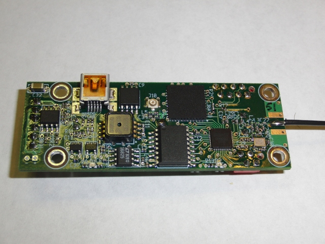
Elements on this side include the new 100μF cap in the upper left corner which sits on the 3.3V supply to try and keep the CPU alive through minor power glitches. Below that is a new package containing a pair of FETs for the ejection circuits. We used discrete FETs in v0.1, but this device has better specs for our needs (lower on resistance, etc). The USB connector was pulled in-board far enough to keep it from hanging over the edge. Right of that is the new data logging chip, and right of that is a U.FL connector in case you want to use an external GPS antenna. We supply power to that connector as most external GPS antennas include their own LNA. And, of course, to the right of that is the Skytraq Venus 634 GPS receiver.
Below and to the right of the GPS receiver is the cc1111, to the left lies the accelerometer and then the barometric pressure sensor above the 5V boost regulator which powers the accelerometer. We haven't found any high-G accelerometers that run on 3.3V yet. Finally the two tiny 5-pin chips are the USB LiPo charger and the 3.3V regulator. What you can't see easily are a pile of 0402 passive components scattered across the board. Even close up, they're hard to pick out by eye.
The only hardware 'bug' was in the reset logic -- the new board was designed with a much larger capacitor on the reset line than the old board. The debug code would only hold the reset line low for a brief instant, sufficient for the old capacitor value but not the new one. Instead of fixing the code, Bdale decided to try a smaller capacitor value and found that it worked just fine. After that, the board came up just fine and the updated firmware was flashed into the CPU.
TeleMetrum v0.2 Software
The only significant software change was that the data logging part changed from a 25LC1024 1Mbit eeprom to an AT45DB161D 16Mbit DataFlash. This required writing a new driver, but fortunately much of the code could be copied from the 25LC1024 driver. Because the AT45DB161D comes from a family of similar-but-different parts ranging from 1Mbit to 64Mbits, I decided to make the code automatically adapt to the installed part, detecting which one was attached and adjusting the driver.
The story here is that the configuration data didn't appear to be getting preserved across reboots -- we use the last block of the data logging part to hold configuration data, including call sign, sensor calibration values and flight parameters. A bit of testing and we found that the code to read/write the device worked perfectly. It turns out that a premature optimization in detecting which kind of flash part was installed had a race condition when multiple threads were trying to access storage at the same time, resulting in the configuration data being left uninitialized. Oops!
The TeleMetrum firmware has a clever hack for selecting between ground mode (for fetching data from the device or altering the configuration) and flight mode (prepared to fly the rocket). It switches between these by detecting whether the board is upright (flight mode) or not (idle mode). However, the accelerometer must be calibrated to tell the difference. What never occurred to us was that if the calibration data was broken enough, the device might always come up in flight mode. In that mode, it isn't listing to either USB or the radio link, so it's impossible to fix the accelerometer calibration data.
A bit of brainstorming led to a fairly simple hack -- check to see if one of the pins on the companion connector was shorted to ground at power on time, if so, force the computer to enter idle mode. Pin 1 of the companion connector is ground, and fortunately, pin 2 was the SPI clock pin, normally output-only, so we could safely use that in this mode as any companion device shouldn't ever pull that low.
Future Events
As of this evening, three boards are built and mostly tested; the radios appear to work, GPS tracks satellites and the beeper makes plenty of noise. Still to check is whether the deployment circuits will fire an ematch (we've tested the design before, just not this specific implementation).
Next weekend, we're off to linux.conf.au in Wellington, New Zealand where we're scheduled to give a presentation on the hardware and software in TeleMetrum. We'll have v0.2 boards to show off, so come and see them in person.
With v0.1, we used the same board design for both flight computer and ground station, TeleDongle. For TeleDongle, we just left most of the components off of the board and loaded alternate firmware. For v0.2, we're planning on building a separate TeleDongle board; that design is finished but no boards are made yet.
Once we're happy with the design, we've got big plans to get more boards made so we can let a few friends buy them for use them in their own rocket projects. That should happen in the next month or so. Once we've gotten enough testing done, and made sure that other people can actually operate them without hand-holding from us, we'll make them available for sale to the general rocket-flying public.
Beyond that, we've got plans to build more stuff:
A stand-alone ground station, called TeleTerra, that would include an LCD readout and flight data recording so you wouldn't need a laptop during the flight.
A companion board, called TelePyro, to control 8 additional pyro channels. These could be used for almost anything from air starts to staging or any other whacky plans.