With embedded systems gaining high resolution displays and powerful CPUs, the desire for sophisticated graphical user interfaces can be realized in even the smallest of systems. While the CPU power available for a given power budget has increased dramatically, these tiny systems remain severely memory constrained. This unique environment presents interesting challenges in graphical system design and implementation. To explore this particular space, a new window system, TWIN, has been developed. Using ideas from modern window systems in larger environments, TWIN offers overlapping translucent windows, anti-aliased graphics and scalable fonts in a total memory budget of 100KB.
Researchers at the HP Cambridge Research Laboratory are building a collection of sub-PDA sized general purpose networked computers as platforms for dissociated, distributed computing research. These devices include small LCD or OLED screens, a few buttons and occasionally some kind of pointing device.
One of the hardware platforms under development consists of a TMS320 series DSP (200MHz, fixed point, 384KB on-chip RAM), 8MB of flash memory, an Agilent ADNS-2030 Optical mouse sensor, a Zigbee (802.15.4) wireless networking interface and an Epson L2F50176T00 LCD screen (1.1", 120 x 160 color). At 200MHz, this processor is capable of significant computation, but 384KB holds little data.
In contrast, early graphical user interfaces for desktop platforms was more constrained by available CPU performance than by memory. Early workstations had at least a million pixels and a megabyte of physical memory but only about 1 MIPS of processing power. Software in this environment was much more a matter of what could be made fast enough than what would fit in memory.
While the X window system[7] has been ported to reasonably small environments[2], a minimal combination of window system server, protocol library and application toolkit consumes on the order of 4 to 5MB of memory, some ten times more than is available in the target platform.
Given the new challenge of providing a graphical user interface in these tiny devices, it seemed reasonable to revisit the whole graphical architecture and construct a new system from the ground up. The TWIN window system (for Tiny WINdow system) is the result of this research.
The hardware described above can be generalized to provide a framework within which the TWIN architecture fits. By focusing on specific hardware capabilities and limitations, the window system will more completely utilize those limited resources. Of course, over-constraining the requirements can limit the potential target environments. Given the very general nature of existing window systems, it seems interesting to explore what happens when less variation is permitted.
The first assumption made was that little-to-no graphics acceleration is available within the frame buffer, and that the frame buffer is attached to the CPU through a relatively slow link. This combination means that most drawing should be done with the CPU in local memory, and not directly to the frame buffer. This has an additional benefit in encouraging synchronized screen updates where intermediate rendering results are never made visible to the user. If the CPU has sufficient on-chip storage, this design can also reduce power consumption by reducing off-chip data references.
The second limitation imposed was to require a color screen with fixed color mapping. While this may appear purely beneficial to the user, the software advantages are numerous as well. Imprecise rendering operations can now generate small nearly invisible errors instead of visibly incorrect results through the use of anti-aliased drawing. With smooth gradations of color available, there is no requirement that the system support dithering or other color-approximating schemes.
Finally, TWIN assumes that the target machine provides respectable CPU performance. This reduces the need to cache intermediate rendering results, like glyph images for text. Having a homogeneously performant target market means that TWIN need support only one general performance class of drawing operations. For example, TWIN supports only anti-aliased drawing; non-antialiased drawing would be faster, but the CPUs supported by twin are required to be fast enough to make this irrelevant.
The combined effect of these environmental limitations means that TWIN can provide significant functionality with little wasted code. Window systems designed for a range of target platforms must often generalize functionality and expose applications to variability which will not, in practice, ever been experienced by them. For example, X provides six different color models for monochrome, colormapped and static color displays. In practice, only TrueColor (separate monotonic red, green, blue elements in each pixel) will ever be used by the majority of X users. Eliminating choice has benefits beyond the mere reduction of window system code, it reflects throughout the application stack.
Windowing can be thought of as the process of simulating multiple, separate, two-dimensional surfaces sharing the same display. These virtual surfaces, or `windows,' are then combined into a single presentation. Traditional window systems do this by presenting a `2 .71 .6/ .72' dimensional user interface which assigns different constant Z values to each object so that the windows appear to be stacked on top of one another.
TWIN provides this traditional metaphor through an architecture similar to
the X window system Composite extension in that all applications draw to
off-screen image buffers which are then combined and placed in the physical
frame buffer. This has many advantages:
![]() Rendering performance is decoupled from frame buffer performance. As the
embedded frame buffer controllers include a private frame buffer, the
bandwidth available to the CPU for that memory is quite restricted.
Decoupling these two operations means that rendering can operate at full
main memory speed instead of the reduced video controller memory speed
Rendering operations needn't clip to overlapping windows. Eliminating the
need to perform clipping reduces the complexity and size of the window
system by eliminating the code needed to construct and maintain the clip
list data structures.
Applications need not deal with damage events. In a traditional
clipping-based window system, applications must be able to reconstruct their
presentation data quickly to provide data for newly visible portions of
windows.
Multiple window image formats can be supported, including those with
translucency information. By constructing the physical frame buffer data
from the combination of various window contents, it is possible to perform
arbitrary image manipulation operations on those window contents, including
translucency effects.
Rendering performance is decoupled from frame buffer performance. As the
embedded frame buffer controllers include a private frame buffer, the
bandwidth available to the CPU for that memory is quite restricted.
Decoupling these two operations means that rendering can operate at full
main memory speed instead of the reduced video controller memory speed
Rendering operations needn't clip to overlapping windows. Eliminating the
need to perform clipping reduces the complexity and size of the window
system by eliminating the code needed to construct and maintain the clip
list data structures.
Applications need not deal with damage events. In a traditional
clipping-based window system, applications must be able to reconstruct their
presentation data quickly to provide data for newly visible portions of
windows.
Multiple window image formats can be supported, including those with
translucency information. By constructing the physical frame buffer data
from the combination of various window contents, it is possible to perform
arbitrary image manipulation operations on those window contents, including
translucency effects.
In the model supported in the X window system by the Composite extension, an external application is responsible for directing the system in constructing the final screen image from the off-screen window contents. TWIN has a simpler model where window contents are composited together through a fixed mechanism. This, of course, eliminates significant complexity but at the cost of also eliminating significant generality. TWIN does not, and is not likely to, support immersive 3D environments.
TWIN tracks rectangular regions of modified pixels within each window. When updating the screen, a single scanline of intermediate storage is used to compute new screen contents. The list of displayed windows is traversed and any section* of the window overlapping the scanline is painted into the intermediate scanline. When complete, the scanline is sent to the frame buffer. This single scanline provides the benefits of a double buffered display without the need for a duplicate frame buffer.
The availability of small color screens using either LCD or OLED technologies combined with sufficient CPUpower have encouraged the inclusion of a rendering model designed to take maximal advantage of the limited pixel resolution available. Anti-aliasing and sub-pixel addressing is used to produce higher fidelity renderings within the limited screen resolution. Per-pixel translucency is included to `see through' objects as well as permit arbitrary object shapes to minimize unused space on the screen.
The complete drawing stack provides a simacrulum of the PDF 1.4 drawing environment, complete with affine transforms, color image blending and PostScript path construction and drawing tools. Leveraging this classic and well known environment ensures both that developers will feel comfortable with the tools and that the system is `complete' in some informal sense.
TWIN uses the rendering operational model from 8 .71 .6/ .72[5], the window system developed for the Plan 9 operating system by Cox and Pike, the same as used in the X render extension[4]. This three-operand rendering operator forms the base upon which all drawing is built:
dst = (src IN mask) OVER|SOURCE dst
The IN, OVER and SOURCE operators are as defined by Porter and Duff.[6] By manipulating the operands, this single operator performs all of the rendering facilities in the TWIN system. Geometric operations are performed by constructing a suitable mask operand based on the shape of the geometry.
Pixel data are limited in TWIN to three formats, 8 bit alpha, 32 bit ARGB and 16 bit RGB. Limiting formats in this way along with the limited number of operators in the rendering equation provided an opportunity to instantiate each combination in custom compositing code. With three formats for each operand and two operators, there are 54 different rendering functions in 13KB of code.
For geometric operations, TWIN uses the model from PostScript as implemented in the cairo graphics system.[8] `Paths' are constructed from a sequence of lines and Bézier splines. An arbitrary path can be convolved with a convex path to construct a new path representing the original path as stroked by the convex path. The convolution operation approximates the outline of the Minkowski sum of the two paths.
A path can then be drawn by scan converting it to a mask for use in the
rendering operation described above. Because the rendering operation can
handle translucency, this scan conversion operation does anti-aliasing by
sampling the path in a 4![]() 4 grid over each pixel to compute
approximate coverage data. This sampling grid can be easily adjusted to
trade quality for performance.
4 grid over each pixel to compute
approximate coverage data. This sampling grid can be easily adjusted to
trade quality for performance.
The application interface includes an affine transformation from an arbitrary 16.16 fixed point coordinate space to 12.4 fixed point pixel space. The 16.16 fixed point values provide reasonable dynamic range for hardware which does not include floating point acceleration. The 12.4 fixed point pixel coordinates provide sufficient resolution to accurately reproduce object geometry on the screen. Note that the screen is therefore implicitly limited to 4096 pixels square.
Providing text at multiple sizes allows the user interface to take maximal advantage of the limited screen size. This can either be done by storing pre-computed glyphs at multiple sizes or preparing glyphs at run-time from scalable data. Commercial scalable font formats all represent glyphs in outline form. The resulting glyph is constructed by filling a complex shape constructed from lines and splines. The outline data for one face for the ASCII character set could be compressed to less than 7KB - significantly smaller than the storage needed for a bitmap face at a single size.
However, a straightforward rasterization of an outline does not provide an ideal presentation on the screen. Outline fonts often include hinting information to adjust glyph shapes at small pixel sizes to improve sharpness and readability. This hinting information requires significantly more code and data than the outlines themselves, making it impractical for the target device class.
An alternative representation for glyphs is as stroke data. With only the path of the pen recorded, the amount of data necessary to represent each glyph is reduced. More significantly, with the stroke width information isolated from the stroke path, it is possible to automatically adjust the stroke positions to improve the presentation on the screen. A secondary adjustment of the pen shape completes the hinting process. The results compare favorably with fully hinted outline text.
An additional feature of the stroke representation is that producing oblique and bold variants of the face are straightforward; slanting the text without changing the pen shape provides a convincing oblique while increasing the pen width produces a usable bold.
The glyphs themselves have a venerable history. The shapes come from work done by Dr A.V. Hershey for the US National Bureau of Standards. Those glyphs were designed for period pen plotters and were constructed from straight line segments on a relatively low resolution grid. The complete set of glyphs contains many different letterforms from simple gothic shapes to letters constructed from multiple parallel strokes that provide an illusion of varying stroke widths. Many additional decorative glyphs were also designed.
From this set of shapes, a simple gothic set of letters, numbers and punctuation was chosen. Additional glyphs were designed to provide a complete ASCII set. The curves within the Hershey glyphs, designed as sequences of short line segments, were replaced by cubic splines. This served both to improve the appearance of the glyphs under a variety of transforms as well as to reduce the storage required for the glyphs as a single cubic spline can replace many line segments. Figure 1 shows a glyph as originally designed with 33 line segments and the same glyph described as seven Bézier splines. Storage for this glyph was reduced from 99 to 52 bytes.
Given the desire to present text at a variety of sizes, the glyph shapes need to undergo a scaling transformation and then be rasterized to create an image. Unless this scaling is restricted to integer values, the edges of the resulting strokes will not necessarily align with the pixel grid. The resulting glyphs will appear fuzzy and will be hard to read.
To improve the appearance of the glyphs on the screen, a straightforward mechanism was developed to reposition the glyph control points to improve the rasterized result. The glyph data was augmented to include a list of X and a list of Y coordinates. Each `snap' list contains values along the respective axis where some point within the glyph is designed to lie on a pixel boundary. These were constructed automatically by identifying all vertical and horizontal segments of each glyph, including splines whose ends are tangent to the vertical or horizontal.
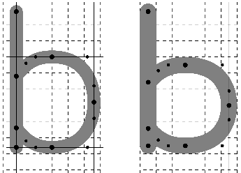
The glyph coordinates are then scaled to the desired size. The two snap lists (X and Y) are used to push glyph coordinates to the nearest pixel grid line. Coordinates between points on a snap list are moved so that the relative distance from the nearest snapped coordinates remain the same. The pen width is snapped to the nearest integer size. If the snapped pen width is odd, the entire glyph is pushed .71 .6/ .72 a pixel in both directions to align the pen edges with the pixel edges. Figure 2 shows a glyph being hinted in this fashion.
The effect is to stretch or shrink the glyph to align vertical and horizontal strokes to the pixel grid. Glyphs designed with evenly spaced vertical or horizontal stems (like `m') may end up unevenly spaced; a more sophisticated hinting systems could take this into account by preserving the relative spacing among multiple strokes.
With the window system supporting a single screen containing many windows, the toolkit extends this model by creating a single top-level widget. This top-level widget contains a single box for layout purposes. Each box can contain a number of widgets or other boxes.
Layout within each box is done either horizontally or vertically with an algorithm which comes from the Layout Widget[3] that the author developed for Xt[1] library. Each widget has a natural size and stretch in both directions. The natural size and stretch of a box is computed from the objects it contains. This forms the sole geometry management mechanism within the toolkit and is reasonably competent at both constructing a usable initial layout and adapting to externally imposed size changes.
TWIN was initially developed to run on a custom embedded
operating system. This operating system design initially included simple
cooperative threading support, and TWIN was designed to run different
parts of the window system in different threads:
![]() Input would run in one thread, events were dispatched without queuing
directly to the receiving object.
Each window would have a thread to redisplay the window contents. These
threads would block on a semaphore awaiting a change in application state
before reconstructing the window contents. Per window locks could block
updates until the application state was consistent.
The window system had a separate thread to compose the separate window
contents into the final screen display. The global redisplay thread would
block on a semaphore which the per-window redisplay threads would signal
when any window content changed. A global system lock could block updates
while any application state was inconsistent.
Input would run in one thread, events were dispatched without queuing
directly to the receiving object.
Each window would have a thread to redisplay the window contents. These
threads would block on a semaphore awaiting a change in application state
before reconstructing the window contents. Per window locks could block
updates until the application state was consistent.
The window system had a separate thread to compose the separate window
contents into the final screen display. The global redisplay thread would
block on a semaphore which the per-window redisplay threads would signal
when any window content changed. A global system lock could block updates
while any application state was inconsistent.
This architecture was difficult to manage as it required per-task locking between input and output. The lack of actual multi-tasking of the application processing eliminated much of the value of threads.
Once this was working, support for threading was removed from the custom operating system.
With no thread support at all, TWIN was redesigned with a global event loop monitoring input, timers and work queues. The combination of these three mechanisms replaced the collection of threads described above fairly easily, and the complexities of locking between input and output within a single logical task were removed.
Of course, once this was all working, the custom operating system was replaced with ucLinux.
While the single thread model works fine in ucLinux, it would be nice to split separate out tasks into processes. Right now, all of the tasks are linked into a monolithic executable. This modularization work is underway.
A window system is responsible for collecting raw input data from the user in the form of button, pointer and key manipulation and distributing them to the appropriate applications.
TWIN takes a simplistic approach to this process, providing a single immutable model. Pointer events are delivered to the window containing the pointing device. Transparent areas of each window are excluded from this containment, so arbitrary shapes can be used to select for input.
TWIN assumes that any pointing device will have at least one associated signal - a mouse button, a screen touch or perhaps something else. When pressed, the pointing device is `grabbed' by the window containing the pointer at that point. Motion information is delivered only to that window until the button is released.
Device events not associated with a pointer, such as keyboards, are routed to a fixed `active' window. The active window is set under application control, such as when a mouse button press occurs within an inactive window. The active window need need not be the top-most window.
Under both the original multi-threaded model and the current single-threaded model, there is no event queueing within the window system; events are dispatched directly upon being received from a device. This is certainly easy to manage and allows motion events to be easily discarded when the system is too busy to process them. However, with the switch to multiple independent processes running on ucLinux, it may become necessary to queue events between the input collection agent and the application processing them.
Within the toolkit, events are dispatched through each level of the hierarchy. Within each box, keyboard events are statically routed to the active box or widget while mouse events are routed to the containing box or widget. By explicitly dispatching down each level, the containing widgets and boxes can enforce whatever policy they like for event delivery, including mouse or keyboard grabs, focus traversal and event replay.
While this mechanism is fully implemented, much investigation remains to be done to explore what kinds of operations are useful and whether portions of what is now application-defined behavior should be migrated into common code.
TWIN embeds window management right into the toolkit. Support for resize, move and minimization is not under the control of an external application. Instead, the toolkit automatically constructs suitable decorations for each window as regular toolkit objects and the normal event dispatch mechanism directs window management activities.
While external management is a valuable architectural feature in a heterogeneous desktop environment, the additional space, time and complexity rules this out in today's Sub-PDA world.
As computing systems continue to press into ever smaller environments, the ability to bring sophisticated user interface technologies along greatly increases both the value of such products as well as the scope of the potential market.
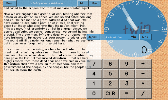
The TWIN window compositing mechanism, graphics model and event delivery system have been implemented using a mock-up of the hardware running on Linux using the X window system. Figure 3 shows most of the current capabilities in the system.
While the structure of the TWIN window system is complete, the toolkit is far from complete, having only a few rudimentary widgets. And, as mentioned above, the port to ucLinux is not yet taking advantage of the multiple process support in that environment. These changes will likely be accompanied by others as TWIN is finally running on the target hardware.
In the x86 emulation environment, the window system along with a small cadre of demonstration applications now fits in about 50KB of text space with memory above that limited largely to the storage of the off-screen window contents. Performance on a 1.2GHz laptop processor is more than adequate; it will be rather interesting to see how these algorithms scale down to the target CPU.
The current source code is available from via CVS, follow the link from http://keithp.com. The code is licensed with an MIT-style license, permitting liberal commercial use.
This document was generated using the LaTeX2HTML translator Version 2002-2-1 (1.70)
Copyright © 1993, 1994, 1995, 1996,
Nikos Drakos,
Computer Based Learning Unit, University of Leeds.
Copyright © 1997, 1998, 1999,
Ross Moore,
Mathematics Department, Macquarie University, Sydney.
The command line arguments were:
latex2html -antialias -white -dir twin-ols2005.www -split 0 -no_navigation twin-ols2005.tex
The translation was initiated by Keith Packard on 2005-06-09