Keith Packard
XFree86 Core Team, SuSE Inc.
keithp@keithp.com
The X Rendering Extension addresses many of the shortcomings inherent in the core X rendering architecture without adding significantly to the protocol interpretation or implementation burden within the server. By borrowing fundamental image compositing notions from the Plan 9 window system and providing sophisticated and extensible font rendering, XFree86 is now much more able to support existing applications while encouraging new developments in user interfaces. More work remains to be done in areas where best practice is less well established, including precise polygon rasterization and image transformations.
At the 2000 Usenix conference, the author presented a paper [Pac00a] which discussed the problems inherent in the core X rendering architecture along with some proposals on what a solution might look like. The fundamental problem was that the rendering system had codified practice that was, in hindsight, soon to be obsolete. A rush to release the original X11 standard left no time for research that could have resolved some technical problems. Perhaps the most important issue was that the hardware of that era was not fast enough for the window system to provide a more sophisticated model to interactive applications.
Some of the proposals in last year's paper--alpha compositing, anti-aliasing, sub-pixel positioning and trapezoids--are included in this new extension. Other parts of the extension, most notably the client-side font management, have been developed during the design of the extension.
The development of this extension has occurred in an entirely open fashion, with input solicited from all areas of the window system community. People involved with XFree86, KDE, Qt, Gdk, Gnome and OpenGL all contributed to the final architecture.
Some areas of the specification are still not complete and the implementation is under construction, but Render has already become an important part of the XFree86 distribution as toolkit and application development starts to take advantage of its presence. It has also delivered a strong message that XFree86 is ready and able to carry the development of the X Window System forward into the future.
The X Rendering Extension (Render) [Pac00b] diverges from the core X [SG92] rendering system by replacing the pixel-value based model with an RGB model. While pixel values are still visible to the client, every pixel value, even those stored in pixmaps, has an associated color value. This provides a natural color-based imaging base while still allowing applications to see the pixel values when necessary.
One compromise resulting from this change involves pseudo-color visuals. The best practice would be to dynamically allocate colors to most closely match the displayed colors. However, the number of pseudo-color desktops is dwindling, so a static color model is used instead. This significantly reduces the implementation burden while still allowing applications to run on pseudo-color hardware. (In fact, the current XFree86 implementation is without even this simplified support and yet no bug reports have been filed to date.)
Along with the presentation of image data as color values, Render supplants the raster-op manipulations of the core protocol with the image compositing operators formally defined by Porter and Duff in 1984 [PD84]. These operators manipulate color data in a natural way by introducing transparency and allowing color data to mix as images are rendered atop one another.
The Porter-Duff compositing model unifies the usual notion of translucency, where a pixel is entirely covered with a non-opaque value, with the notion of partial coverage, where a portion of the pixel is covered while the remaining portion is uncovered. Render uses partial coverage to approximate anti-aliasing; partially covered pixels along the edge of geometric objects are rendered as if they were translucent.
All of the operations in Render are specified in terms of the primitive compositing operators, yielding a consistent model and allowing a minimal implementation. The rendering model is designed to work well with modern toolkits and applications by providing necessary server-resident operations in as simple a fashion as possible.
Physically, translucent objects absorb some, but not all, of the light passing through them. The color of the object affects which wavelengths are most strongly absorbed. Visually, translucent objects appear to affect the color and brightness of objects beyond them.
The effect of an opaque object partially obscuring the field of view is similar; at fine enough resolution, the color sampled at a point near the edge of the object will appear as a mixture of the overlying and underlying object colors. Porter and Duff used this property to translate partial coverage into translucency.
The effect of light on a translucent object can be simulated by blending the color of the translucent object with that of objects beyond it. When dealing with computer images, translucency can be described as a mathematical operation on the color data of a collection of images. The Porter and Duff compositing model consists of formulae which use color data in conjunction with a per-pixel opacity value called ``alpha''. With these formulae many intuitive image manipulations can be performed.
Each of the operators defined by Porter and Duff operate independently on each of the color channels in each pixel. The equations are abbreviated to show the operation on a single channel of a single pixel.
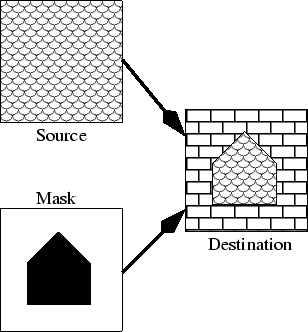
A common compositing operation is to place one image over another.
Transparent areas of the overlying image allow the underlying image to show
through. Opaque areas hide the underlying image while translucent areas
blend the two images together. By defining the ``alpha'' of a pixel as a
number from 0 to 1 measuring its opacity, a simple equation combines two
pixel colors together:
Another common operation is to mask an image with another; transparent areas
in the mask are removed from the image while opaque areas of the mask leave
the image visible.
One important aspect of this model is that it creates a new image description which attaches another value ``alpha'' to each pixel. This value measures the ``opacity'' of the pixel and can be operated on by the rendering functions along with the color components.
Sometimes it is useful to create composite images which are themselves
translucent, in other words, contain alpha values. This effect can be
achieved by augmenting the operators with an operation which produces a
composite alpha value along with the color values. For the ``over''
operator, the composite alpha value is defined as:
Visible in the above equations for computing the ``over'' operator is the
asymmetry in the computation of alpha and the color components:
The Plan 9 Window System, designed by Russ Cox and Rob
Pike [Pik00], provides a unified rendering operation based
Porter-Duff compositing:
Using this basic rendering primitive, the extension defines geometric operations by specifying the construction of an implicit mask which is then used in the general primitive above. Anti-aliased graphics can be simulated by generating implicit masks with partial opacity along the edges.
As with most X extensions, Render adds a number of X-server resident datatypes to encapsulate the notions expressed above:
PictFormats hold information needed to translate pixel values into red, green, blue and alpha channels. The server has a list of picture formats corresponding to the various visuals on the screen along with additional formats that represent data in various formats stored in pixmaps. There are two classes of formats, Indexed and Direct. Indexed PictFormats hold a list of pixel values and RGBA values while Direct PictFormats hold bit masks for each of R, G, B and A.
Direct PictFormats may contain all of R, G, B and A or they may contain only R, G and B or only A. These latter two provide the necessary formats for separate alpha masks and for server visuals which have no destination alpha channel.
Each Indexed PictFormat has an associated colormap from which the associated color values are allocated. This allows multiple different Indexed formats to coexist by allowing applications to select the best matching format and selecting the associated colormap for windows rendered in that format.
Pictures connect an X Drawable (Window or Pixmap) with a suitable PictFormat. They also serve as a convenient place to place rendering state that is related to the picture. When the PictFormat does not provide an alpha channel, the Picture may refer to an external alpha channel which is represented as another Picture, of which only the alpha channel is used. Without this external alpha channel, the Picture has an implicit alpha value of 1 for each pixel.
Pictures are the universal pixel data representation within Render. There are no explicit pixel values provided to any operation. To provide for solid colors or repeating patterns, Pictures have a `Repeat' attribute, when set, the picture is treated as an infinite source of data by tiling the contents of the picture along both axes.
This allows solid color filling, tiling and stippling to be a special case of object-to-object data copying.
One additional property allows for the optimization of image presentation on
displays with known sub-pixel geometry. In such environments, applications
need control over the compositing of each color component. The usual
compositing operator blends all four components using the same alpha value.
When the ![]() picture operand in the compositing primitive has the
`ComponentAlpha' attribute set, the R, G, B and A values are interpreted as
alpha values operating on each channel in isolation.
picture operand in the compositing primitive has the
`ComponentAlpha' attribute set, the R, G, B and A values are interpreted as
alpha values operating on each channel in isolation.
At the heart of the Render extension lies a single request: all other rendering is defined in terms of the Composite request which performs the basic composite rendering operation described in Section 2.2. This operator is defined in the Render specification as follows:
Composite
	op:		OP
	src:		Picture
	mask:		Picture (or None)
	dst:		Picture
	src-x, src-y:	Int16
	mask-x, mask-y:	Int16
	dst-x, dst-y:	Int16
	width, height:	Card16
This request combines the specified rectangle of src and mask with the specified rectangle of dst using op as the compositing operator. The coordinates are relative to their respective drawable's origin. Rendering is clipped to the geometry of the dst drawable and then to the dst clip-list, the src clip-list and the mask clip-list.
If the specified rectangle extends beyond src, then if src has the repeat attribute set, the src picture will be tiled to fill the specified rectangle. Otherwise rendering is clipped to the src geometry.
If the specified rectangle extends beyond mask, then if mask has the repeat attribute set, the mask picture will be tiled to fill the specified rectangle, otherwise rendering is clipped to the mask geometry.
If src, mask and dst are not in the same format, and one of their formats can hold all without loss of precision, they are converted to that format. Alternatively, the server will convert each operand to the fallback format.
If mask is None, it is replaced by a constant alpha value of 1.
When dst has clip-notify set, a NoExpose event is sent if the rendering operation was not clipped by either src or mask, otherwise a sequence of GraphicsExpose events are sent covering areas in dst where rendering was clipped by src or mask.
Some important notes on this definition:
As Pictures provide the only representation for pixel data within Render, application generated images must use the existing core X PutImage request to transmit that information to the server. A future extension could provide new image transfer functions that would eliminate the intermediate buffer as well as offer standard image compression algorithms to reduce bandwidth consumed by bulk image data in a networked environment.
Font management and text rendering has always been a source of frustration from both implementors and application developers. X attempted to abstract fonts into simple bitmap images along with associated data described either as simple strings or integer values. Rasterization of the images was left up to the X server and application access to advanced font information, such as kerning tables and ligatures, was not possible through the standard X interfaces.
Many applications, when faced with the X text model simply gave up and implemented all text rendering entirely within the application, sending the resulting rendered images to the X server. The X text rendering code was relegated to drawing labels for buttons and dialog messages. This is not a very efficient use of the tremendous acceleration potential of most graphics systems.
While struggling with building a similar system for the Render extension, several factors converged to redirect development in an entirely new direction. The first was a realization that applications would need direct access to complete font information, preferably the raw font file itself. Only with such direct access could applications be assured that all of the information about the font would be available to them.
An initial Render proposal provided this access by extending the existing X Font Services protocol. Applications and the X server would share font data via the X font server with applications requesting advanced font properties with complex new requests. Taking existing font file formats and generalizing the information so that a single format could encapsulate all information was a daunting task that I put off while developing the simple image composition parts of the extension.
The second factor which changed the direction of the text system was a discussion about PDF files and embedded font data. As with other applications, the display of PDF files requires the presentation of fonts available only to the application. The only portable mechanism for using application provided fonts within the existing font framework is to have the application use the X Font Services protocol by creating a custom font server within the application. This adds another point of failure for all X applications as they now become unwittingly dependent on this font server whenever they access fonts; adding a large number of such applications will significantly reduce the performance for all applications when manipulating font names.
One goal for Render was to solve this problem in a more straightforward fashion. The obvious solution is to have the application build a font from data it provided, sending glyph images through the X protocol stream instead of through the back door with the X Font Services protocol.
The final factor evolved from a discussion about Unicode encoded fonts. Before a single glyph can be drawn, an X client receives geometric information for every glyph in the font, as well as the minimum and maximum values over the entire font. When using outline fonts, the only way this information can be obtained is to first rasterize every single glyph. For a font with 256 glyphs, this is not a tremendous burden. Encodings containing Han glyphs may contain thousands of glyphs, causing some performance concerns. Unicode fonts can potentially contain millions of glyphs. At this point, it becomes impractical to rasterize all of the glyphs and deliver all of this information to the application, especially when only a small fraction of the font is ever likely to be displayed.
Any new text system would need to be designed to allow the incremental rasterization of glyphs. The problem with incrementally rasterizing glyphs within the X server is that applications would need to incrementally request information about the glyphs, which would entail making extra round-trips at the protocol level. Round trips are a serious performance problem in a networked environment, and this performance penalty would be felt at application startup (which is already a sore point with some X applications).
These factors--the delivery of sophisticated font information, client-generated fonts and the need to incrementally rasterize fonts without increasing the number of round trips--lead to a very simple solution. The X Rendering Extension has no font support. Instead, it provides a mechanism for applications to cache glyph images within the server and rasterize a sequence of them. Applications are responsible for locating fonts, rasterizing glyphs and generating geometric information on their own.
This resolves all three problems while reducing the complexity of the extension. Applications have direct access to the font files, and thus to all of the information contained therein. As all fonts are client-supplied, embedded fonts in PDF documents are handled as efficiently as any other fonts. Finally, there are no round trips for font handling at all. This reduces application startup time, as no requests are made of the X server to list available fonts or query font information. It also reduces typical network traffic, as only the glyphs actually used by the application transit the network connection. The extra traffic consumed by glyph images is more than compensated for by the lack of glyph metric information for glyphs never drawn on the screen.
Measurements of typical application performance, presented in Section 4.3, show marked decreases both in application startup time and network utilization, even when using 8 bits for each pixel in the glyphs.
The elimination of server-side fonts within Render presents some new challenges. Applications still need a concise and efficient way of rendering a sequence of glyphs along a fixed baseline. Render provides for the storage of multiple Glyphs in groups known as `GlyphSets'. Each Glyph is essentially a Picture with additional geometric information that describes where the glyph should be drawn relative to the baseline and an offset to the next glyph.
Glyphs are named within GlyphSets by arbitrary 32-bit numbers: there is no presumed encoding. These names are transmitted in 8, 16 or 32 bit encodings: there is no variable length encoding provided.
Within the current XFree86 implementation, identical glyphs share the same storage. This works within a GlyphSet, and among multiple GlyphSets from one or more clients. This eliminates the server-side storage overhead for having clients provide their own glyphs.
The duplicate rendering and transmission of glyphs can be ameliorated by having multiple applications cooperate in the rasterization of glyphs for particular fonts. The author envisions a cooperative shared-memory mechanism where applications in the same address space can work together to build the needed glyphs. Because the names used to refer to the GlyphSets within the X server have a lifetime no greater than the X connection which created the name, the Render protocol allows each client to have its own name for each GlyphSet. The GlyphSet exists as long as any name exists.
Significant infrastructure and architecture will need to be designed for this kind of sharing. As these changes will not impact the Render protocol itself, this design can be done when a demonstrated need exists.
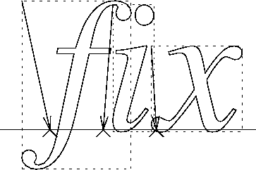
Once the needed glyphs are delivered to the X server, the client renders sequences of them with one of the CompositeGlyphs requests (there are three, corresponding to the three glyph name encodings). These requests render a number of glyph lists, each of which is offset from the previous by positional deltas along both axes. Changes to the selected glyph set may be interspersed among the glyph lists. This is very much like the core X text rendering requests with the additional generalization of vertical position adjustments. The position adjustments have also been extended from 8 to 16 bits. An example of simple text rendering is shown in Figure 2. The glyph positions are marked along the baseline with carets while the extent of each glyph image is outlined with a dashed box. Each glyph contains the distance from the upper left corner of the glyph image to the rendering origin, the dimensions of the glyph image and the distance from rendering origin to the location where the next glyph is to be drawn.
When approximating anti-aliasing, a sequence of separate operations using
the ![]() operator generates inaccurate values when more than one
operation covers the same area with alpha values that are neither
transparent nor opaque. The problem is that the sub-pixel geometry of the
two objects is lost in the conversion to a coverage value.
operator generates inaccurate values when more than one
operation covers the same area with alpha values that are neither
transparent nor opaque. The problem is that the sub-pixel geometry of the
two objects is lost in the conversion to a coverage value.
The ![]() operator assumes that the sub-pixel coverage by two
objects is best approximated by assuming that each object covers the same
fraction of the other object as of the pixel as a whole. When drawing text,
a better approximation is to assume that the glyphs do not actually overlap;
the overall area of coverage within the pixel is thus the sum of the areas
covered by each pixel.
operator assumes that the sub-pixel coverage by two
objects is best approximated by assuming that each object covers the same
fraction of the other object as of the pixel as a whole. When drawing text,
a better approximation is to assume that the glyphs do not actually overlap;
the overall area of coverage within the pixel is thus the sum of the areas
covered by each pixel.
The glyph drawing requests allow an optional intermediate Picture object to
be created; all of the glyphs in the request are rendered to this
intermediate Picture using an ![]() operator. The resulting image
is then rendered to the destination using the operator specified in the
request. The server is free to eliminate the intermediate Picture object
when the rendering result would not be affected by its use, such as when the
glyphs are represented with only a single bit per pixel or when none of the
glyphs overlap.
operator. The resulting image
is then rendered to the destination using the operator specified in the
request. The server is free to eliminate the intermediate Picture object
when the rendering result would not be affected by its use, such as when the
glyphs are represented with only a single bit per pixel or when none of the
glyphs overlap.
With glyphs rasterized within the client and transmitted to the X server, there is an obvious concern that these glyphs will represent an additional burden placed on the network. While the glyph images will indeed increase the traffic sent from the client to the server, the traffic in glyph metrics from the server to the client will be eliminated.
It turns out that for typical application execution, the elimination of the glyph metrics and font names transmitted from the server to the client more than compensates for the additional traffic represented by the glyph images. Table 1 shows the network utilization for two common applications using Latin fonts with fewer than 256 glyphs.
Of interest is the large number of bytes needed to simply select appropriate fonts; this is represented by the ListFonts requests and replies. As the core X architecture provides only primitive string-based font matching, more sophisticated schemes must be implemented within the client, necessitating the transmission of information about available fonts from the server.
Moving from small Latin-1 encoded fonts to larger Han or Unicode fonts will significantly increase the amount of metric data transmitted, while not significantly increasing the amount of glyph data: large parts of the Han or Unicode character set will not be used.
It is important to note that the core X architecture requires a round trip to list or open fonts. As applications typically open many fonts at startup time, these additional round trips can dramatically increase the time it takes to initialize the application.
The elimination of font handling within the X server shifts the burden of font file management to the client. Disparate mechanisms for font management among different clients is not (usually) desirable leading to the need for a standard font file access library. Building on the well designed FreeType library, the Xft library provides for common font naming, font file management and font customization. Xft is not a part of the Render extension itself, but is an essential part of the overall architecture for providing font access to applications.
Xft also allows some level of compatibility with older X servers by presenting a unified API that uses the core requests to approximate the results generated with the Render extension. Applications can detect when this happens to allow them to compensate. Fortunately, as XFree86 becomes even more pervasive, the number of legacy X servers should continue to decrease making this compatibility largely unnecessary.
An important premise of the design of Xft was that the library should not hide the underlying rasterization engine and font files from the applications. Any attempt to abstract this access would only serve to prevent applications from taking full advantage of the capabilities present within the font files and rasterization engine.
There is an obvious conflict present here - on one hand, Xft provides enough abstraction to mask the differences between core X fonts and Render based glyphs, and on the other it provides complete access to an underlying font file if present. Applications will need to prepare for either eventuality and act accordingly. The expectation is that Xft will be used by toolkit libraries, which would be responsible for managing this distinction if necessary.
Selecting fonts is a two part process: first locating an appropriate face and then applying additional attributes that modify the face to create the right glyph images. Once this has been done, attributes about the font are passed back to the application.
Xft unifies these steps into one mechanism. An XftFontName is a typed property list; each element has a name and a value. Each available face is represented by an XftFontName containing the properties of the face as provided by the underlying font mechanism.
Applications construct XftFontNames and present them to the API. The library matches this name with the available faces to select the best face and then presents the additional properties to the rasterizer to adjust the final glyph presentation. The resulting font has an associated name which contains additional information about the font, such as the file from which the face was loaded.
While the internal representation of a name is a property list, it is
convenient for existing applications to have a string representation which
can be converted into the internal representation. The general format
for Xft font name strings is:
The pieces of Render described above above are not very controversial; they codify existing practice from other systems which is known to work well. They have also been in use for some time, providing some reasonable assurances as to their value. Two further components of the extension are less well understood and currently not implemented within XFree86. These components, polygon rendering and image transformation, are discussed next, presenting both resolved and outstanding issues with current thinking.
Taking cues from OpenGL [SAe99], Render reduces the geometric objects to be rendered by the server to a minimal set. Complex objects are tesselated within the client and sent to the server as a set of primitive objects. This minimizes the implementation effort within the server along with the effort needed to test the conformance of an implementation while not penalizing applications too severely.
Render provides two separate primitive objects; triangles and trapezoids. Both are defined in terms of 32-bit fixed point numbers which use 24 bits for the integer portion of the value and 8 bits for the fractional portion. This allows much more precise location of the vertices for polygons and eliminates a significant source of visual noise caused when objects are snapped to an integer grid.
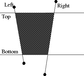
Triangles are specified by locating their three vertices using these coordinates. Trapezoids are more complex as they are designed to accurately represent the tesselations used by PostScript [Ado85] and Gdk. Trapezoids are represented by two horizontal lines delimiting the top and bottom of the trapezoid and two additional lines specified by arbitrary points, as shown in Figure 3. Any area between the four lines is a trapezoid (or, in the degenerate case, a triangle). Allowing points not coincident with the top or bottom of the trapezoid makes the edges of multiple trapezoids sharing the same edges align precisely; the same line can be used for all of the trapezoids irrespective of the horizontal extents of those objects.
The rasterization of polygons seems like a non-controversial problem; connect a sequence of vertices with lines and fill the covered area. However, a consequential issue does arise: the specification of an appropriate level of rendering precision.
The first question which arises is whether the precise pixelization of polygons should be specified in the standard. The core X protocol requires precise pixelization of all objects, which makes verifying the implementation quite easy, but also essentially eliminated the utility of those objects. The core X specification of most primitives turned out to be too hard to implement efficiently in software, and only some recent hardware has enough flexibility to implement a significant portion in hardware. Very few applications use X geometric objects beyond zero-width lines.
For imprecise rasterization, leaving the pixelization entirely unspecified makes the primitives very difficult to use; applications must accept wide variations in potential presentation. The question is what constraints should be applied to pixelization. OpenGL has relatively weak invariant requirements because of the desire for high-performance mixed software and hardware implementations. Existing applications have stronger requirements for consistent pixelization which require additional constraints.
Precise pixelization places strong requirements on the specification: the pixelization specified must be reasonable to implement as well as reasonable looking. A poor specification can make every implementation useless. A precise specification is also useful for applications that need to mix server side and client side rendering, but only if the specification is straightforward to implement.
Instead of offering only one of these two modes, Render provides both. An imprecise mode designed to map to existing GL-optimized hardware and a precise mode designed to satisfy the needs of applications requiring detailed control over the rendered results on the screen.
Imprecise polygons must match a brief set of invariants:
These constraints are designed to minimize the visual artifacts associated with polygon tesselation and translation. It is believed that these invariants can be satisfied with existing hardware.
Precise polygons present a difficult challenge. For sharp polygons, the specification is straightforward: pixels whose center points fall within the polygon are drawn, those outside are not. Following the X model, pixels whose center lie precisely on an edge are drawn when the polygon interior is to the right, or if on a horizontal edge when the polygon interior is below.
Given a 32-bit coordinate space, this can be implemented exactly using values no larger than 64 bits, and that only for clipping.
For smooth (anti-aliased) polygons, the answer is less certain. The obvious answer of computing the fraction of each pixel covered by the polygon turns out to be computationally expensive; no fewer than 192 bits appear to be required to precisely compute the area covered by a pixel intersected by both sides of the trapezoid.
While this may be better than the computation needed to render wide ellipses from the core protocol, there is no reason to believe that this particular specification is any better than one less expensive to implement. The area covered by a pixel is only a rough approximation to the correct value needed to filter the polygon shape to a collection of pixels; a cheaper specification will be just as ``correct'', as long as it generates essentially the same values.
A current proposal is to split the pixels involved into three groups: pixels entirely covered by the polygon, pixels entirely uncovered by the polygon and pixels partially covered by the polygon. Covered and uncovered pixels generate the obvious results.
For each pixel partially covered by the trapezoid, the coverage is computed
by clipping the trapezoid to the pixel boundaries. Where the trapezoid
edges intersect the boundaries of the pixel, the coordinates are represented
as 16-bit fractional values along the pixel edge. This precision yields
pixel coverage errors of less than 1 part in ![]() while requiring only 32
bit arithmetic for the area computation within the pixel.
while requiring only 32
bit arithmetic for the area computation within the pixel.
Another proposal would be to eliminate precise polygons from the extension, leaving only imprecise polygons. Questions remain about what additional invariants would need to be added to the existing list and whether they would impact hardware acceleration for imprecise polygons.
Which choice makes the most sense may well depend on whether an efficient implementation can be written which captures either the above definition of precise polygons or an alternative precise specification. Lacking an efficient implementation, applications will rapidly gravitate to imprecise polygons, leaving precise polygons as yet another albatross within the X server. 1
There is a single request that renders a set of trapezoids and three requests for rendering triangles. Trapezoids are specified by four bounding lines, a top and bottom horizontal line and two diagonal lines, on the left and right. The trapezoid in Figure 3 shows that the coordinates specifying the left and right edges need not be coincident with the horizontal elements.
The triangle requests differ only in the encoding of the triangle vertices. The request formats are taken from OpenGL APIs. The first form delivers a simple list of triangles with one point per vertex in each triangle. The second uses a list of vertices and combines the last two vertices of a triangle with the next vertex to form another triangle. This operation precedes until the list of vertices is exhausted. The final triangle form combines the first and third vertex of a triangle with the next vertex to form the succeeding triangle.
These requests each operate as implicit mask elements in the base Composite operator. A source Picture provides RGBA elements. Additional requests that provide RGBA values for each vertex replace the source Picture with an implicit Picture generated by interpolating the RGBA vertex colors through the polygon. This allows a wide range of color effects with only a few requests.
The final operation added to Render involves the transformation of image data within the X server. Arbitrary affine transformations provide a wealth of possible manipulations that can be accelerated with hardware traditionally used for 3D texture mapping.
The Transform request takes a quadrilateral area from the source image and maps it to a quadrilateral area within the destination area. Vertices are mapped sequentially which allows an arbitrary affine transformation of the image data from source to dest.
The destination quadrilateral forms an implicit alpha mask which may be used to smooth the edges of the transformed image. The source image is created by filtering the source Picture during the transformation. The precise set of filters to be provided has not yet been determined; the expectation is that common hardware filters should be included along with a few higher quality filters designed with digital signal processing techniques.
The eventual intent is to allow implementations to provide additional filters as needed and to create a mechanism within the protocol to advertise at least some of their characteristics.
There are additional questions about edge effects within the filter execution; perhaps additional filter parameters will be needed to generate pixel values beyond the bounds of the source image.
There is also a proposal to limit the destination to a trapezoid rather than the more general quadrilateral form. This would probably simplify the initial implementation while not overly restricting future optimizations.
The need for the Render extension has been present ever since the X server moved from monochrome to color; the original rendering architecture was never well suited to dealing with color data. However, only with the recent renaissance of X-based application development and consequent reinvigoration of X technology has enough interest and thought been applied to researching what was needed.
Too much weight had been historically given to compatibility with existing X applications and X servers. The two new open source user interface environments, Gnome and KDE, were hamstrung by the existing X rendering system. KDE accepted the limitations of the environment and made the best of them. Gnome replaced server-side rendering with client-side rendering turning the X protocol into a simple image transport system. The lack of hardware acceleration and the destruction of reasonable remote application performance demonstrated that this direction should be supplanted with something providing a modicum of server-side support.
As of Usenix 2000, no formal proposals for a complete extension had been produced and yet considerable interest attended the presentation of a collection of ideas related to this issue. One of the attendees, Rob Pike, described the architecture of the rendering system that he and Russ Cox had developed for the Plan 9 window system. The simple unified architecture from that environment was lifted with only slight extensions to form the core of this new X-based rendering system.
The Render extension protocol was discussed within the XFree86 community for several months. Once it had stabilized, an implementation was started with the goal of producing a workable demonstration of anti-aliased text by August of 2000.
At this point, the implementation provides support only for the basic compositing primitive along with the text primitives. The issues discussed above related to anti-aliased polygon rasterization preclude an implementation of either polygon or image transformation operators. Once that issue has been resolved, the implementation can be completed.
Starting in October of last year, an architecture for accelerating the Render extension has been under development within the XFree86 server. As the protocol has been designed for implementation on modern hardware, the implementation of the primitives themselves has been relatively straightforward. As expected, hardware acceleration provides a tremendous performance benefit. Early measurements of simple image compositing by the author and Mark Vojkovich showed the hardware running as much as forty times faster than reasonably optimized C code.
Late in 2000, Xft support was been integrated into the Qt toolkit, which forms the underpinnings for the K desktop environment. That toolkit provides a complete abstraction for all rendering operations, so the act of modifying the toolkit instantly provided anti-aliased text in all KDE applications. With Qt 3.0, additional Render functionality will be utilized, allowing applications to composite images on the screen.
Some attempts have also been made to utilize Render within the Gnome community. However, until the transition from Gtk+ 1.2 to Gtk+ 2.0, too much of the underlying X font model is exposed to applications to enable a complete transition. Gtk+ 2.0 should be ready within the next year, providing the community with another toolkit free of core X font dependencies.
The X Rendering Extension provides a completely new rendering model for use within the X window system. Its small size and low level primitives permit a relatively modest size implementation while providing complete functionality. The primitives have been designed to closely match both application requirements and hardware capabilities.
The X desktop has already begun a transformation with the introduction of anti-aliased text in several toolkits and application suites. Where toolkits were once struggling to provide modern user interface techniques, Render steps in and permits applications to speak their own language. New applications have been threatening to turn X into a simple image transport protocol; the core rendering system has proven essentially unworkable in the modern world. Render brings graphics back to the server, exposing the capabilities of the hardware while permitting applications to again run efficiently across a network. Render allows the X window system to again support the advancement of the open source desktop environment.
The Render extension has been the work of many people, among them:
Thanks also go to Bart Massey for help in preparing the manuscript.
This document was generated using the LaTeX2HTML translator Version 99.2beta6 (1.42)
Copyright © 1993, 1994, 1995, 1996,
Nikos Drakos,
Computer Based Learning Unit, University of Leeds.
Copyright © 1997, 1998, 1999,
Ross Moore,
Mathematics Department, Macquarie University, Sydney.
The command line arguments were:
latex2html -white -transparent -split 0 -nonavigation xrender.tex
The translation was initiated by Keith Packard on 2001-04-24