
LED Fireworks. Or, parent helpers go overboard
My friend, Mike Ward, and I help out at our kids school by teaching 5th and 6th graders programming in conjunction with a Lego class. For several years, I was teaching Logo on ancient Apple II machines. The teacher had a great curriculum and the kids learned a lot, but this year we decided to switch things around and try them out on Arduinos.
This spring, the kids are building a Lego display centered around a birthday party theme for the star elephant at the Oregon Zoo (Packy), who turned 50 last weekend. In a moment of fun, I suggested that perhaps we should have some fireworks, along with the presents and birthday cake. How hard could it be to wire up a couple of LEDs to an Arduino to make something that looked like fireworks?
Selecting parts.
Mike and I sat down to order some parts from Digikey. We found these nice, cheap, LED drivers from Sharp. Then we found a selection of LEDs from Cree along with current-programming resistors (12.7kΩ) to drive the LEDs at 20mA, and some bypass caps (0.1μF) to keep the parts happy.
The LED drivers are simple shift registers, with separate clock and data. They have both input and output pins, so you can daisy chain them and drive as many as you like from a single pair of CPU pins. We figured 160 LEDs would be plenty, so we ordered 10 chips.
The LED drivers came in a through-hole, DIP package; it seemed like we'd be able to just stuff them into a breadboard and quickly wire things up.
Prototyping the design
The LED driver chips turn out to use a much finer pitch package than the usual 0.1" spacing. There's no way we could stuff them into a breadboard and quickly wire things up. Obviously, a bit more care while ordering would have uncovered this, but my experience with through-hole parts is limited to parts from the mid 1970s…
I soldered extension wires onto one chip to test the circuit, and managed to get one chip talking to an Arduino. Here's a short movie of that in action:
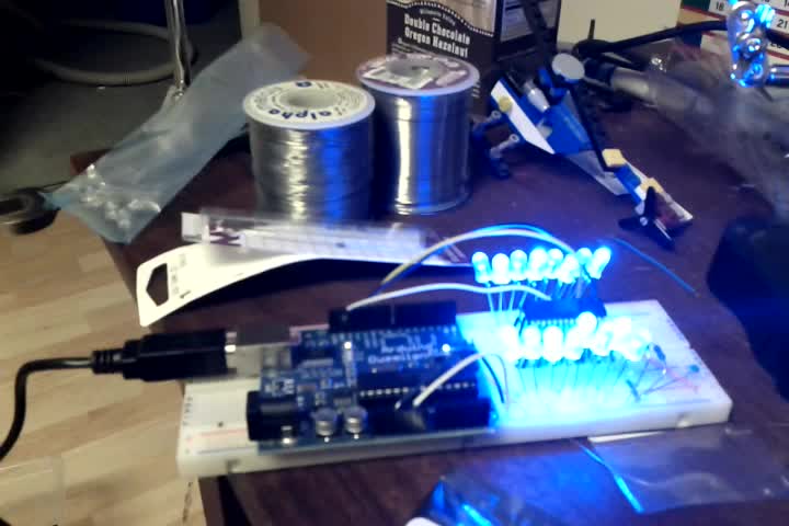
You can see the LED driver chip sitting on a set of extension leads plugged into the breadboard. It's hooked to the SPI port on the Arduino board, with the clock set as fast as it will go. If you watch the video, you can see that the LEDs actually vary in brightness. They're actually being pulse-width modulated. Clocked at 2MHz, there's enough bandwidth in the SPI bus to drive 160 LEDs with 127 discrete pulse widths at nearly 100Hz (100 * 127 * 160 = 2032000).
Is bread boarding practical?
With the chip propped up on its extension wires, and the LEDs plugged in, the whole setup was not surprisingly fragile. Getting five of these chips wired up and running for the length of the Lego show (one day at school and two days at the zoo) seemed unlikely. So, we decided to build some custom circuit boards.
Using the GEDA tools to make circuit boards
My business partner, Bdale Garbee, and I build rocketry electronics through Altus Metrum. He's the hardware guy and I spend my weekends writing firmware for various micro-controllers. Of course, I use free software tools for the firmware, and Bdale uses the free gEDA tools for the hardware. I've gotten vaguely familiar with those by helping Bdale review circuit diagrams and PC board layout over the years. So I figured I'd be able to learn a bit more about them and come up with some designs.
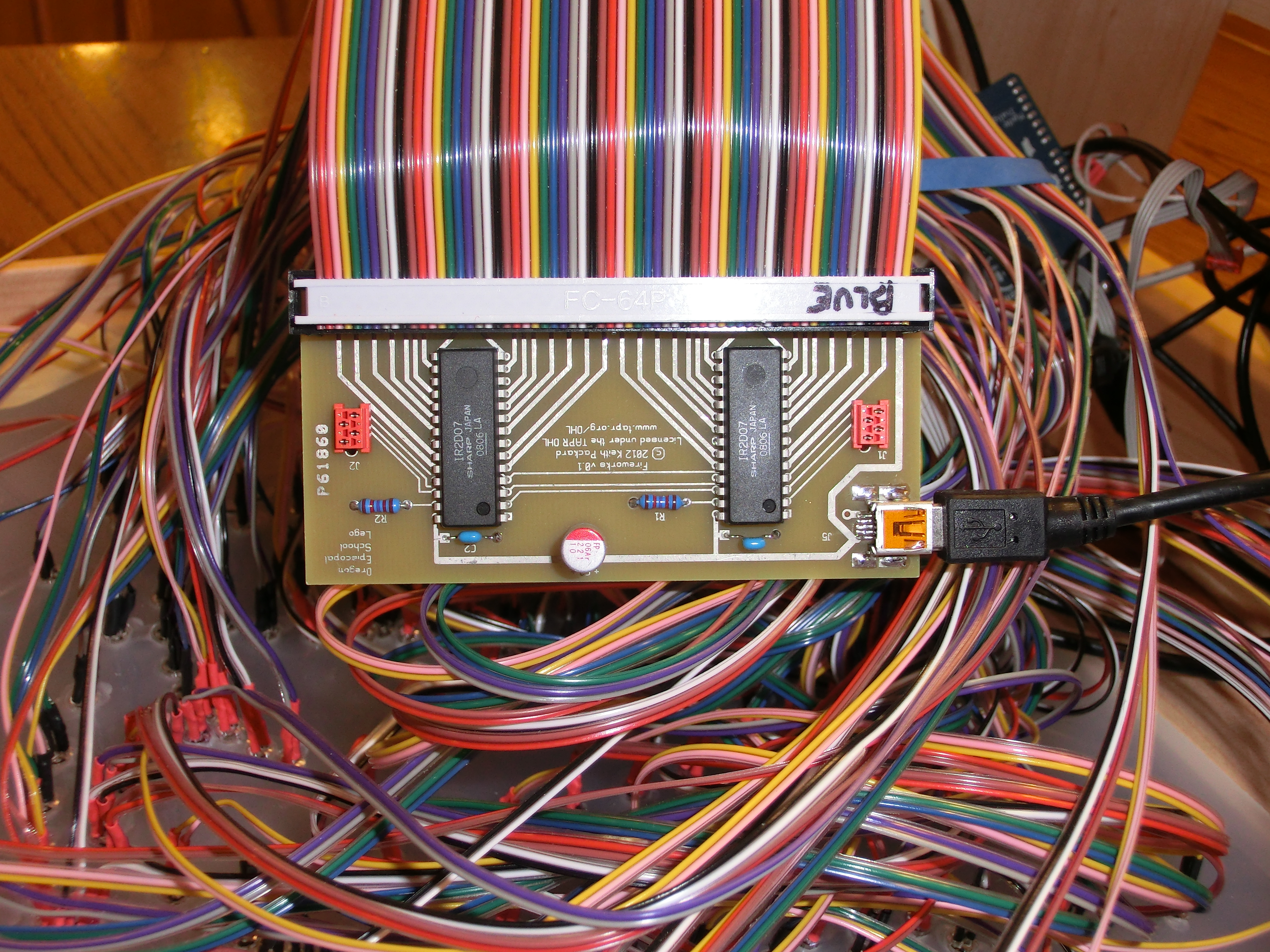
I decided to stick two LED drivers on each board. As the chips can drive each LED with up to 50mA of current, each board could potentially consume 1.6A at 5V. Sticking a linear regulator on each board capable of supplying that much current would have required a hefty heat sink. Instead, I decided to stick a mini USB connector on the board and use some cheap USB power supplies.
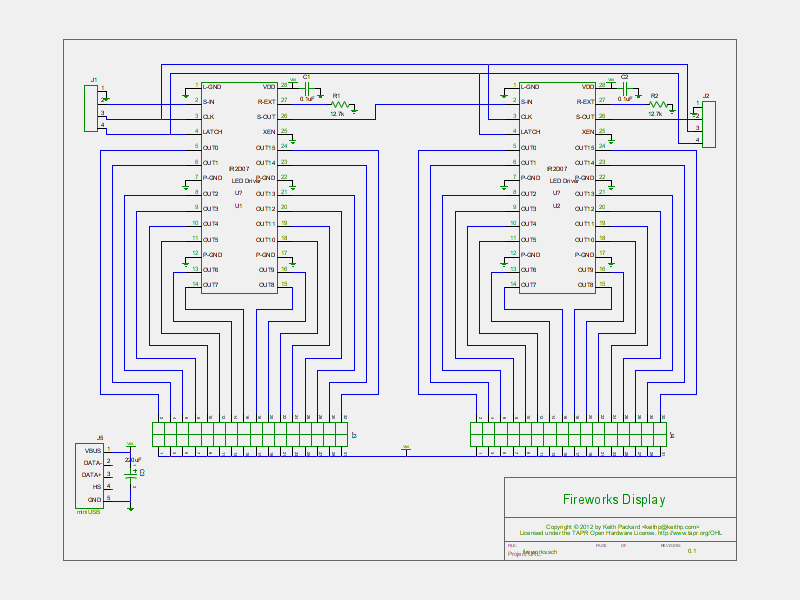
Of course, there wasn't a pre-packaged schematic symbol or footprint for the LED driver, so I first had to construct those. But, with symbols for all of the parts I used available, I drew this circuit:
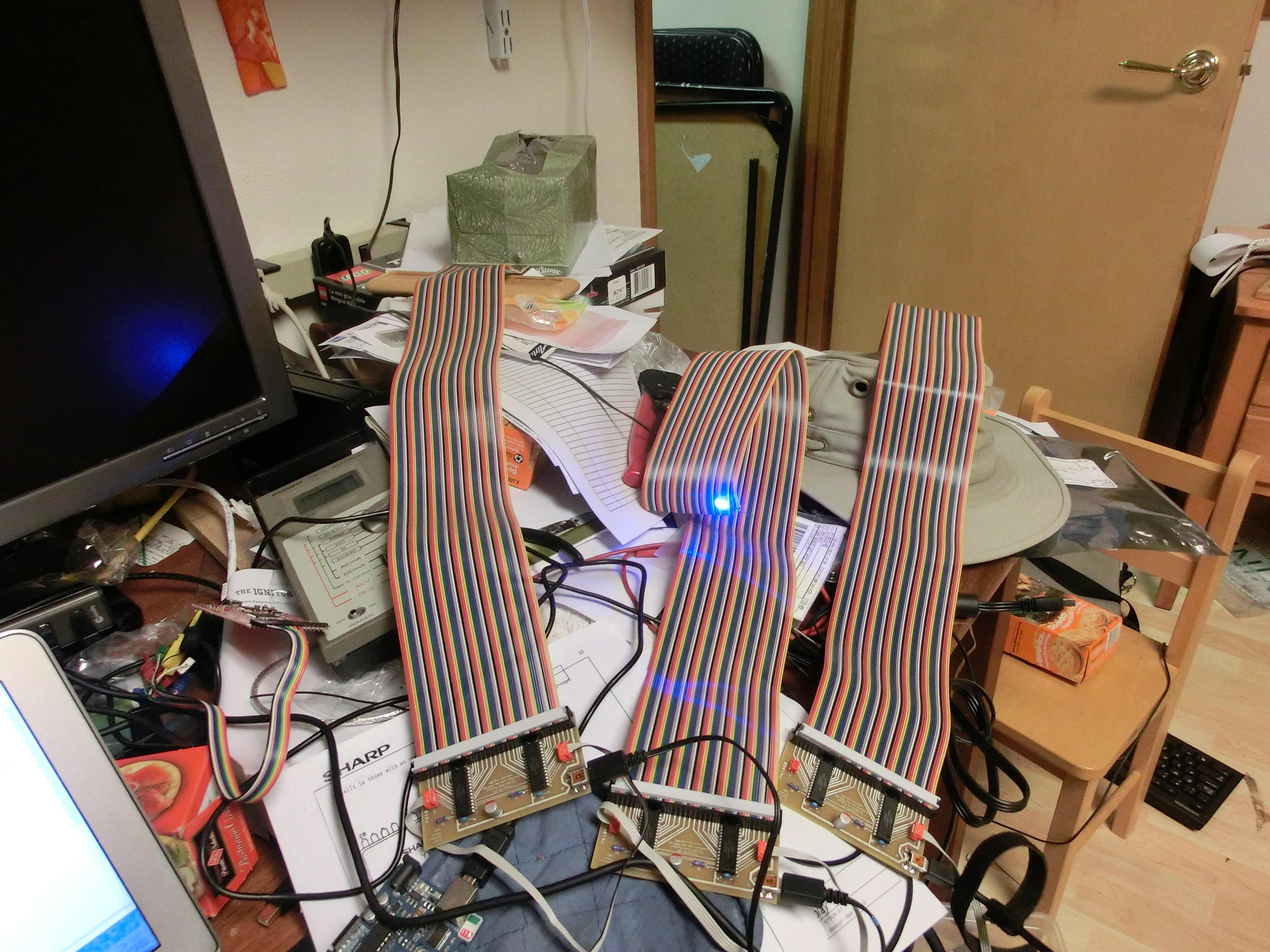
Wiring up 32 LEDs
It's really easy to draw wires showing 32 LEDs hooked up to each board. Actually selecting connectors that can be easily hooked up took a bit more time. The idea of crimping individual two-pin connectors for 160 LEDs didn't seem like fun, plus individual connectors were going to cost a small fortune (the best option I found would have cost about $0.40 per LED). Bdale suggested using ribbon cable with a crimp-on connector -- crimp a connector across the whole cable and then split out two-wire sets for each LED. I'd still have to individually solder each LED to the wire, but on the board end, all I'd have to do is crimp the connector on to the cable.
Designing the circuit boards
The gEDA tools separate schematic design and PCB layout into two separate tools; the schematic program, gschem, exports a netlist and set of components which the schematic program, PCB, can import. This sounded a bit clunky to me, as you have to re-export and re-import the schematic data into the PCB each time you make changes, but it seems to work reasonably well in practice.
The first time the schematic data is imported to the PCB tool, all of the component footprints are simply stacked on top of one another. With those moved to sensible locations, the tool will show 'rats' for each netlist.
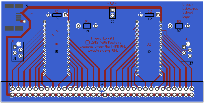
Having drawn the schematic with symbols that strongly resembled the actual components, it was pretty easy to work through the rats one at a time by painting copper on the board. I'd noticed that all of the signals could easily be routed on one side of the board, so I flooded the back side with a ground plane to keep things quiet.
The final circuit board design looks like this:
Circuit boards.
All Altus Metrum products are manufactured by Advanced Circuits, and we've been quite happy with them. They offer a cheap and fast prototyping service through their barebonespcb.com site. These boards are two layers with no silk screen or solder mask.
I uploaded my design and in a couple of days I got back some shiny circuit boards:
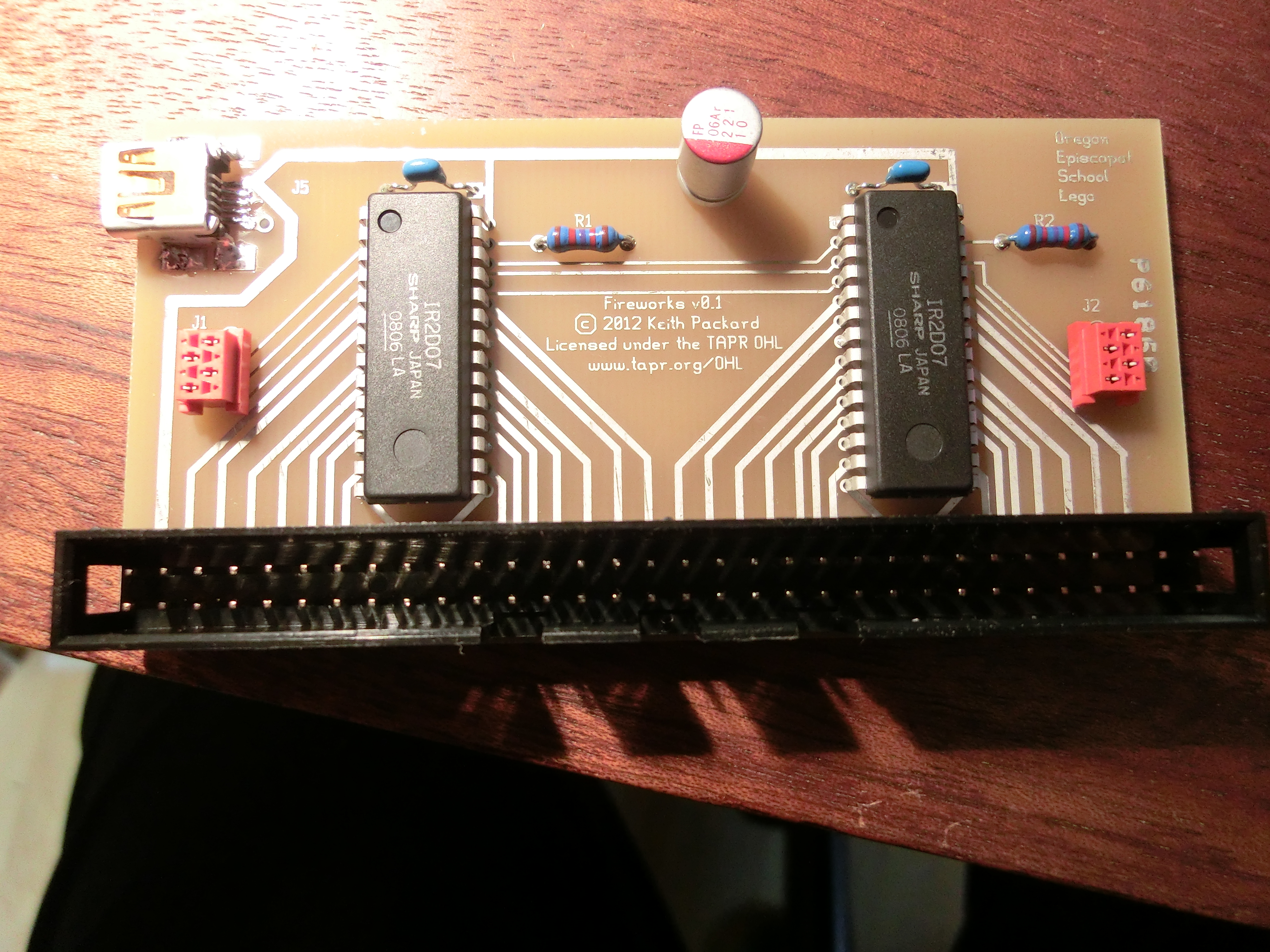
The footprint I designed for the LED drivers turned out to have a very small gap between the pads for each pin and the ground plane. This lead to a couple of shorted pins in the five boards, which were pretty easy to diagnose as the LED driven by that pin would be stuck on.
Here's another picture with the ribbon cable connected and an LED lit up:
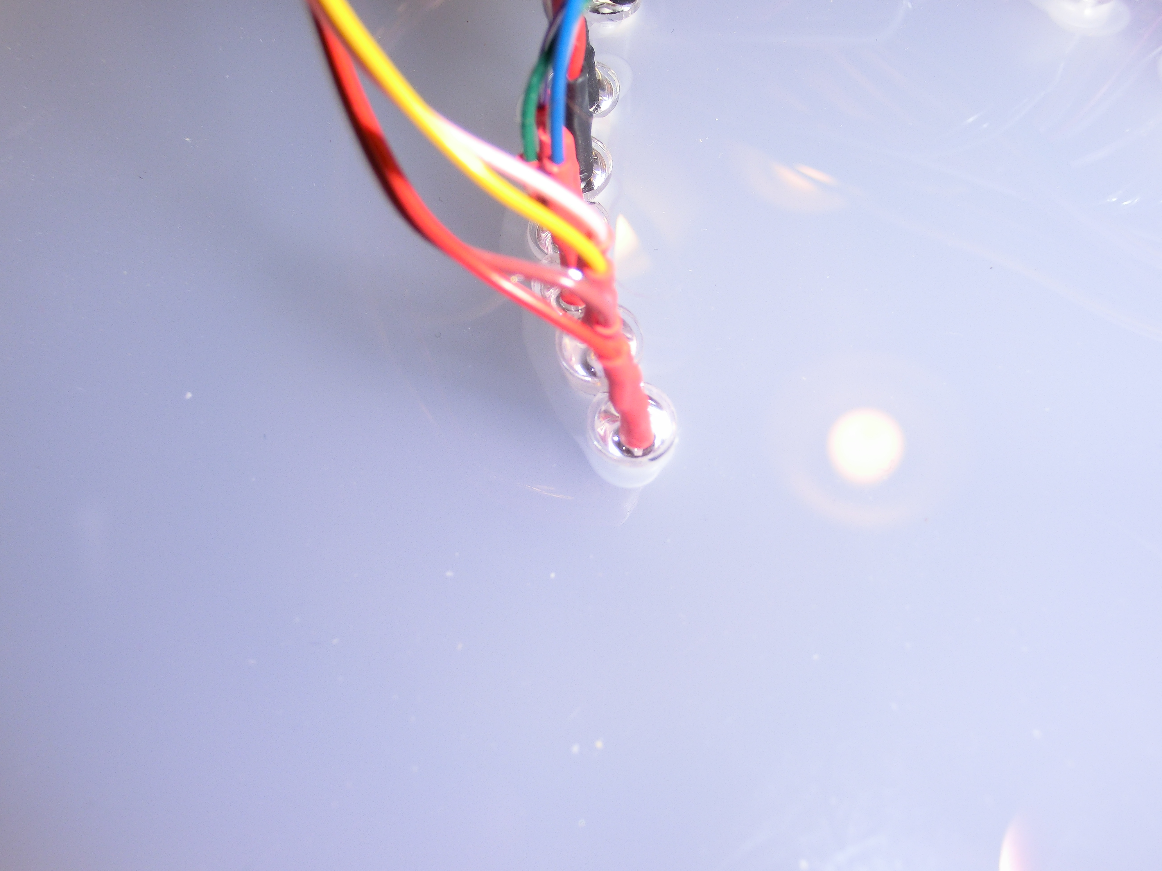
Mounting the LEDs
I started by writing a small nickle program to simulate the trajectory of a ballistic fireworks shell followed by an explosion at apogee and subsequent ballistic tracks for the resulting pieces. I made the initial conditions of the launch somewhat random, and Mike and I sat and watched that draw things until we saw a couple that looked 'good'. The output from that was a series of X/Y locations spaced uniformly in time. Mike used those to drill holes in a piece of acrylic from TAP plastics. He glued the LEDs into that with some white glue (so that we have a chance of getting them back out):
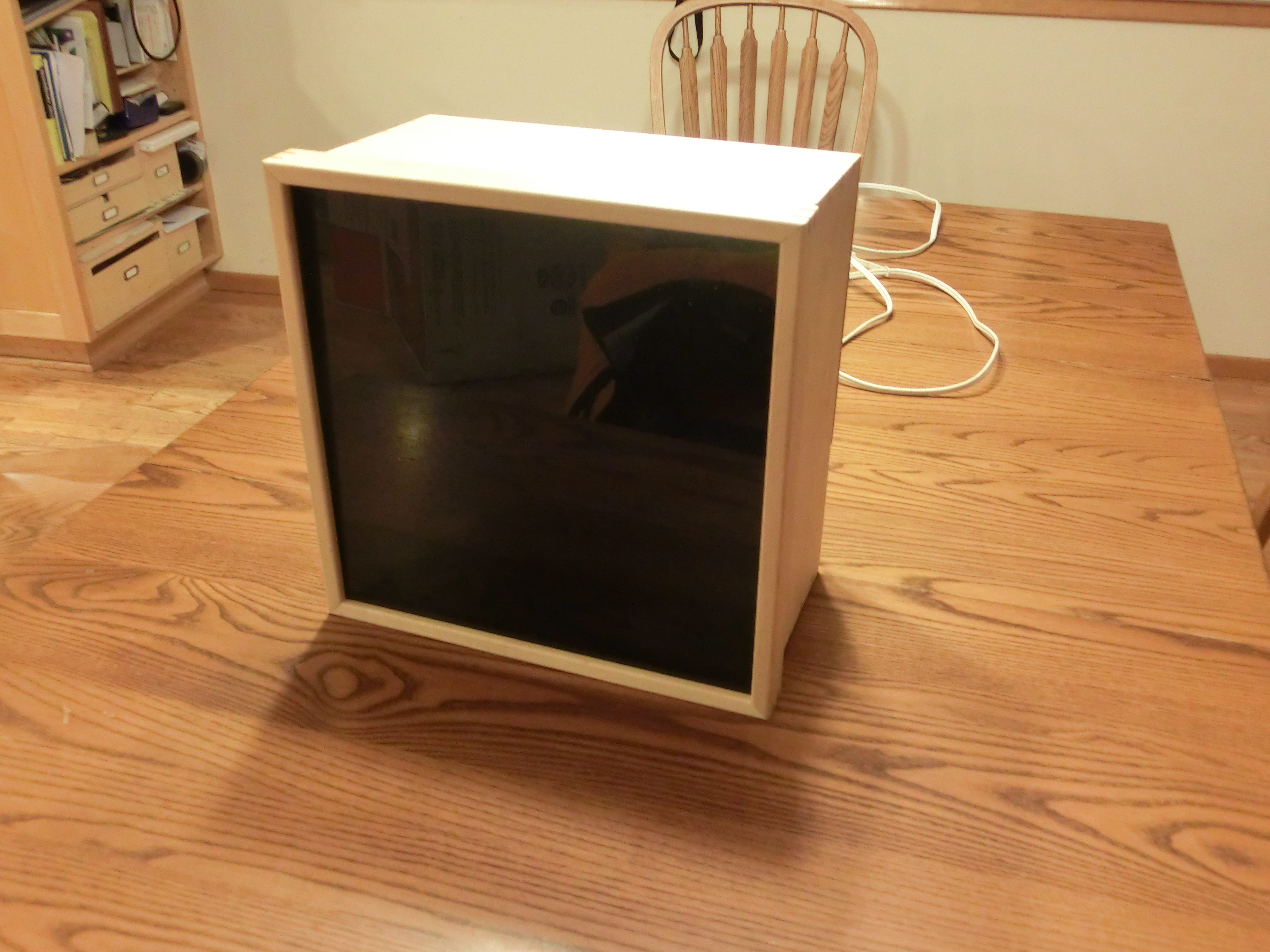
A custom maple box?
I spent last weekend visiting my father for his birthday. Meanwhile, Mike was busy back home building a case for the project. I got home and found that he had fabricated a solid maple case. It's beautiful, and holds all of the LEDs, boards, wires and a couple of 4-outlet USB power supplies.
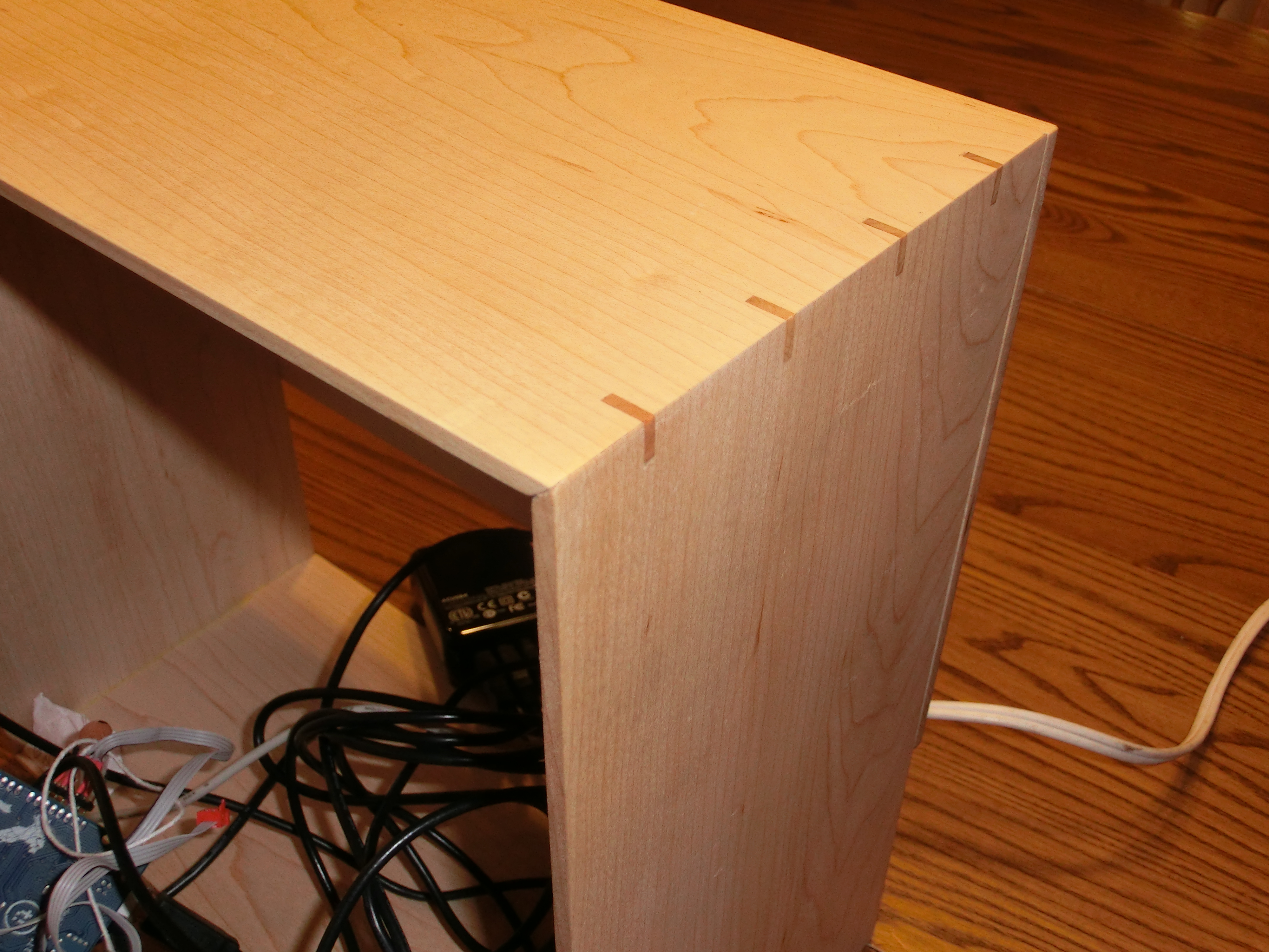
Here's a picture of the joint he made in the box corners:
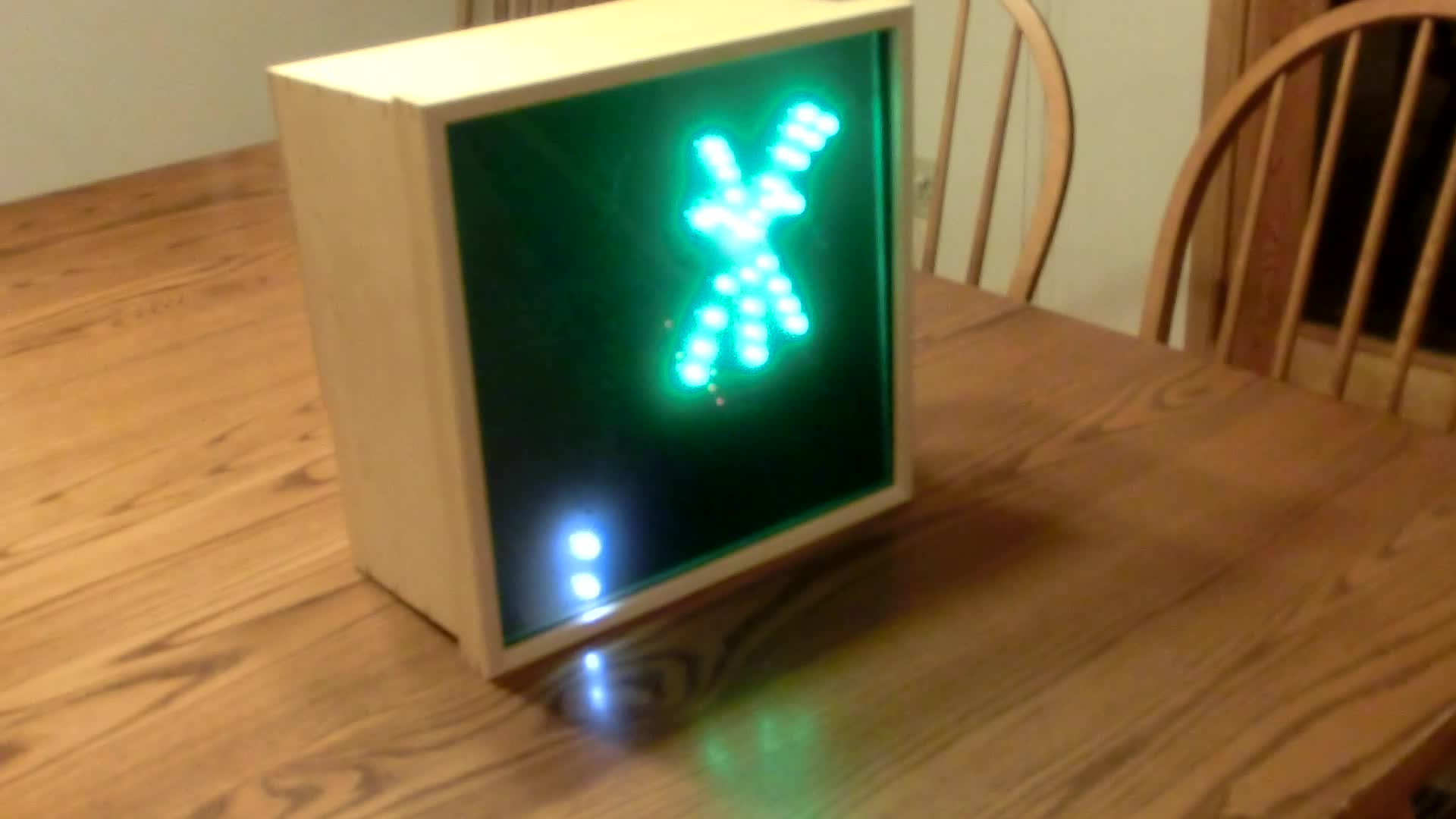
The finished product
Here's the inside of the box:
And here's a movie of the whole thing in action. It's missing 8 white LEDs; I hadn't ordered enough from Digikey.
Downloading schematics and PCB artwork
The hardware design is licensed under the TAPR Open Hardware License. It's all stored in git (of course):
git://keithp.com/git/hw/fireworks
All of the symbols I created are also available through git:
git://keithp.com/git/hw/keithp
Things I'd do differently
One of the frustrating things about moving atoms around instead of just bits is that once you've got a physical artifact, it's really expensive to change it. There are a couple of minor things I would change if I were going to build more of these:
Add mounting holes. Not having any way to mount the boards means that they're flopping around inside the cabinet. We'll probably find a way to tie them down somehow, but a couple of holes in the boards would have made that really easy.
Increase the gap between the pin pads and the ground plane. The narrow space provided ample opportunity for solder bridges. I've increased that spacing in the git repository version of the boards.
Used a variable resistor for LED current control. With a fixed value, it's very difficult to adjust the relative brightness of the LEDs. Even though we used LEDs from the same series, the different colors have different apparent brightness.
Used surface mount passives. We had bought through-hole parts when the plan was to build these on a breadboard, but soldering through-hole parts onto the board is more work than using surface mount parts. 0805 (or even 1206) parts are plenty large to solder by hand and are faster to deal with than having to fold leads, insert them into holes, flip the boards over, solder them down and trim the leads.
Perhaps we went a bit overboard on this project...
Things that worked well
There were a couple of things that went better than I had expected:
The gEDA tools aren't that hard to use. Constructing the circuit board really was a simple matter of painting with copper. If you can drive inkscape, you can make circuit boards.
Advanced Circuits bare-bones PCB service. It was really cool to upload the output files from gEDA and have actual boards arrive in the mail a couple of days later.
Building the boards. I really didn't expect all of the components to 'just fit' in the boards; I figured I'd mess up the footprints or drill sizes and end up kludging something onto the boards. Bdale did catch a small drill size on the LED driver pins, which I bumped up a bit, but other than that, all of the parts slipped in and soldered easily. Each board took about 10 minutes to put together.